Electroconductive member for electrophotography, process cartridge, and electrophotographic apparatus

a technology of electrophotography and electrophotography apparatus, applied in the direction of corona discharge, thin material handling, instruments, etc., can solve the problems of photosensitive member excessive charging, excessive discharge locally, image with blank dots, etc., and achieve high-quality electrophotographic images.

Active Publication Date: 2017-01-24
CANON KK
View PDF28 Cites 30 Cited by
  • Summary
  • Abstract
  • Description
  • Claims
  • Application Information

AI Technical Summary

Benefits of technology

[0014]In addition, the approach of Japanese Patent Application Laid-Open No. H08-272187 involves using an electroconductive fiber in the surface of the charging member. Accordingly, when the charging member of Japanese Patent Application Laid-Open No. H08-272187 is applied as it is to an electroconductive member for electrophotography, local excessive discharge cannot be sufficiently suppressed in some cases. Although the approach of Japanese Patent Application Laid-Open No. H10-186805 exhibits an effect by which a stable void is formed between the charging electrode and the body to be charged, a discharge site is the same as a conventional one. Accordingly, when the electroconductive member of Japanese Patent Application Laid-Open No. H10-186805 is applied as it is to the electroconductive member for electrophotography, an effect enough to stabilize the discharge is not obtained in some cases.
[0015]The present invention has been made in view of such technological background, and the present invention is directed to providing an electroconductive member suppressed in image trouble caused by abnormal discharge independent of its use conditions and use environment. Further, the present invention is directed to providing a process cartridge and an electrophotographic apparatus each of which can stably form a high-quality electrophotographic image over a long time period.
[0019]According to the present invention, independent of the use conditions and use environment of the electroconductive member, even when the electrical resistance value of the electroconductive member cannot be strictly controlled, the occurrence of an image trouble resulting from abnormal discharge can be suppressed by stabilizing discharge.
[0020]Further, according to the present invention, the process cartridge and the electrophotographic apparatus capable of forming a high-quality electrophotographic image can be obtained.

Problems solved by technology

In a charging roller as an example of the electroconductive roller that is placed so as to abut with a photosensitive member in an electrophotographic apparatus and charges the photosensitive member through the application of a direct-current voltage, when the resistance of the charging roller falls short of a proper resistance region, discharge does not stabilize and hence excessive discharge locally occurs in some cases.
At that time, the surface of the photosensitive member locally undergoes excessive charging, and as a result, an image with a blank dot may occur.
Meanwhile, also when the resistance of the charging roller exceeds the optimum resistance region, the discharge does not stabilize and hence a fine horizontal streak-like image failure occurs owing to a discharge failure in some cases.
The foregoing is liable to occur in an ion conductive charging roller that may cause a charging failure particularly under the L / L environment.
As described above, the electron conductive charging roller and the ion conductive charging roller have different features in terms of electrical characteristics, but each involve a problem in that its resistance may deviate from the proper resistance region.
As a result, the discharge becomes instable, which may be responsible for the occurrence of an image trouble derived from abnormal discharge.
In addition, when a charging roller is used in an AC / DC charging system as a system involving applying a voltage obtained by superimposing an alternating-current voltage (AC voltage) on a direct-current voltage (DC voltage) to the charging roller, a spot-like image failure derived from abnormal discharge called a sandy image occurs in some cases.
In the case of a transfer roller as another example of the electroconductive roller as well, an image trouble derived from the abnormal discharge may occur.
As described above, it is difficult to stably control the electrical resistance value of the electroconductive roller such as a charging roller or a transfer roller, and the electrical resistance value needs to be controlled to a proper resistance region.
When the electrical resistance value deviates from the proper resistance region, stable discharge is hardly obtained and hence such various image troubles as described above may occur.
However, it is not easy for the approach of Japanese Patent Application Laid-Open No, 2000-274424 to exploit the merits of both the electron conductive agent and the ion conductive agent at the same time through the combined use thereof.
In addition, in today's circumstances where an increase in speed of an electrophotographic apparatus and the lengthening of its lifetime are required, the proper region of the electrical resistance value tends to narrow, and hence it may be difficult to control the discharge characteristic of the electroconductive roller through the optimisation of the electrical resistance value.

Method used

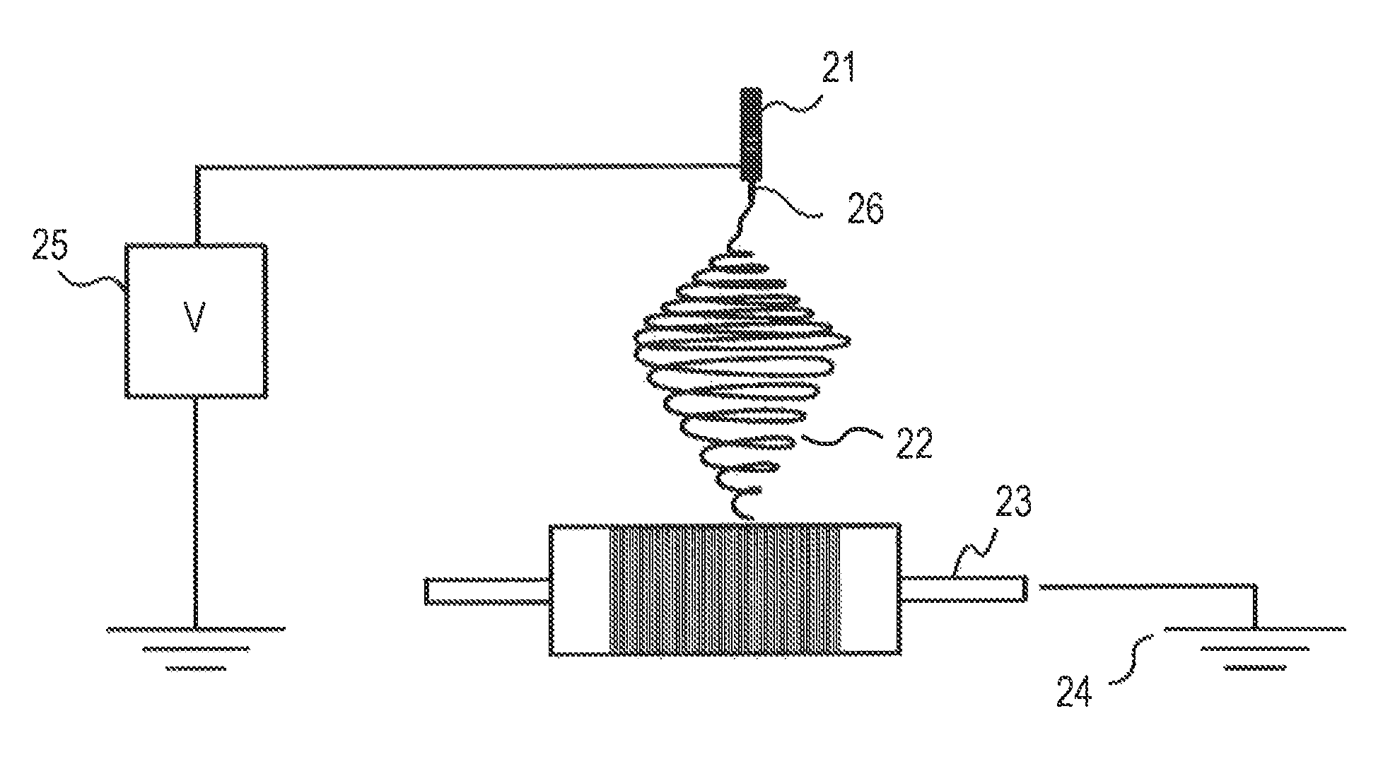
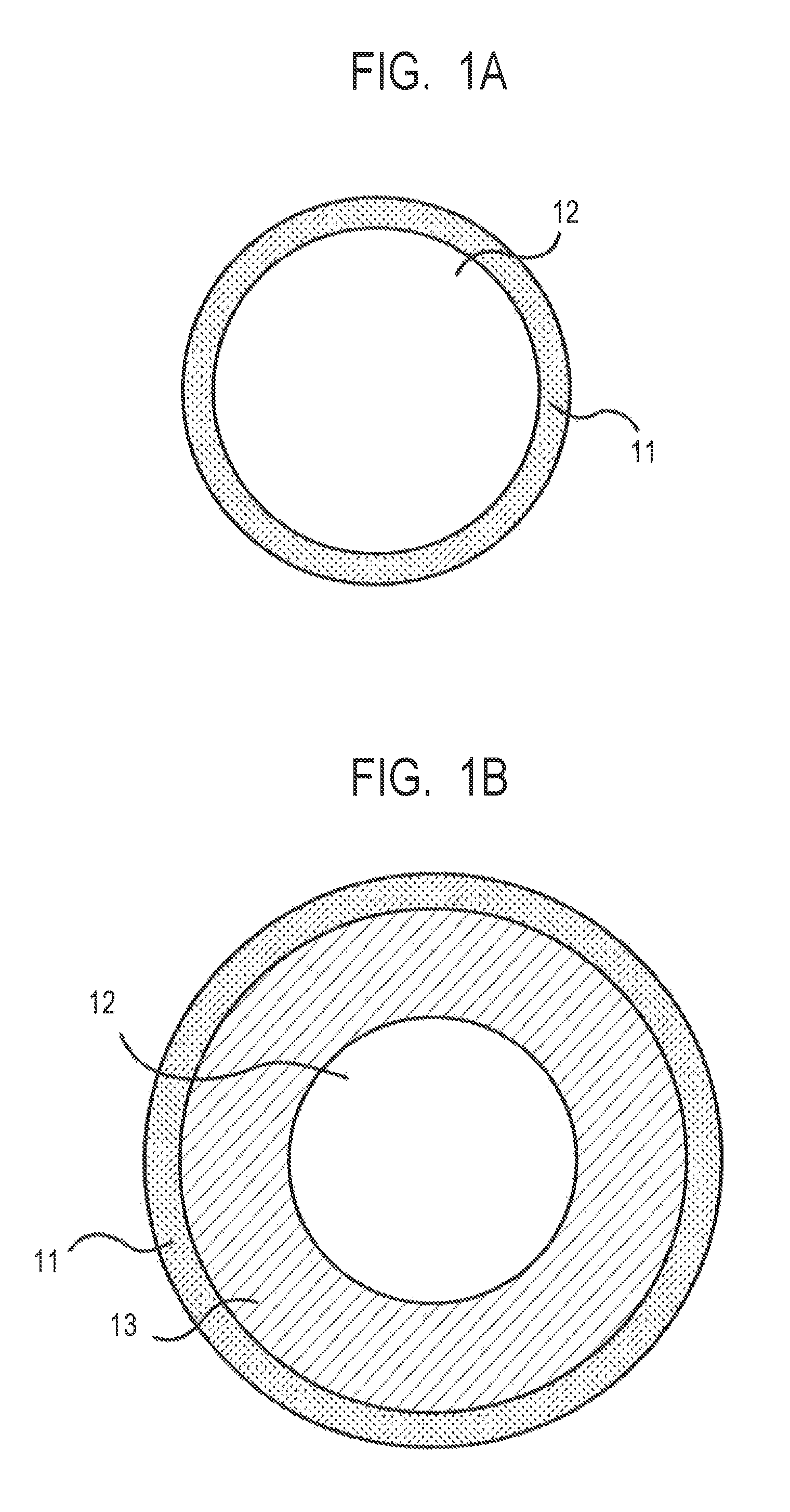
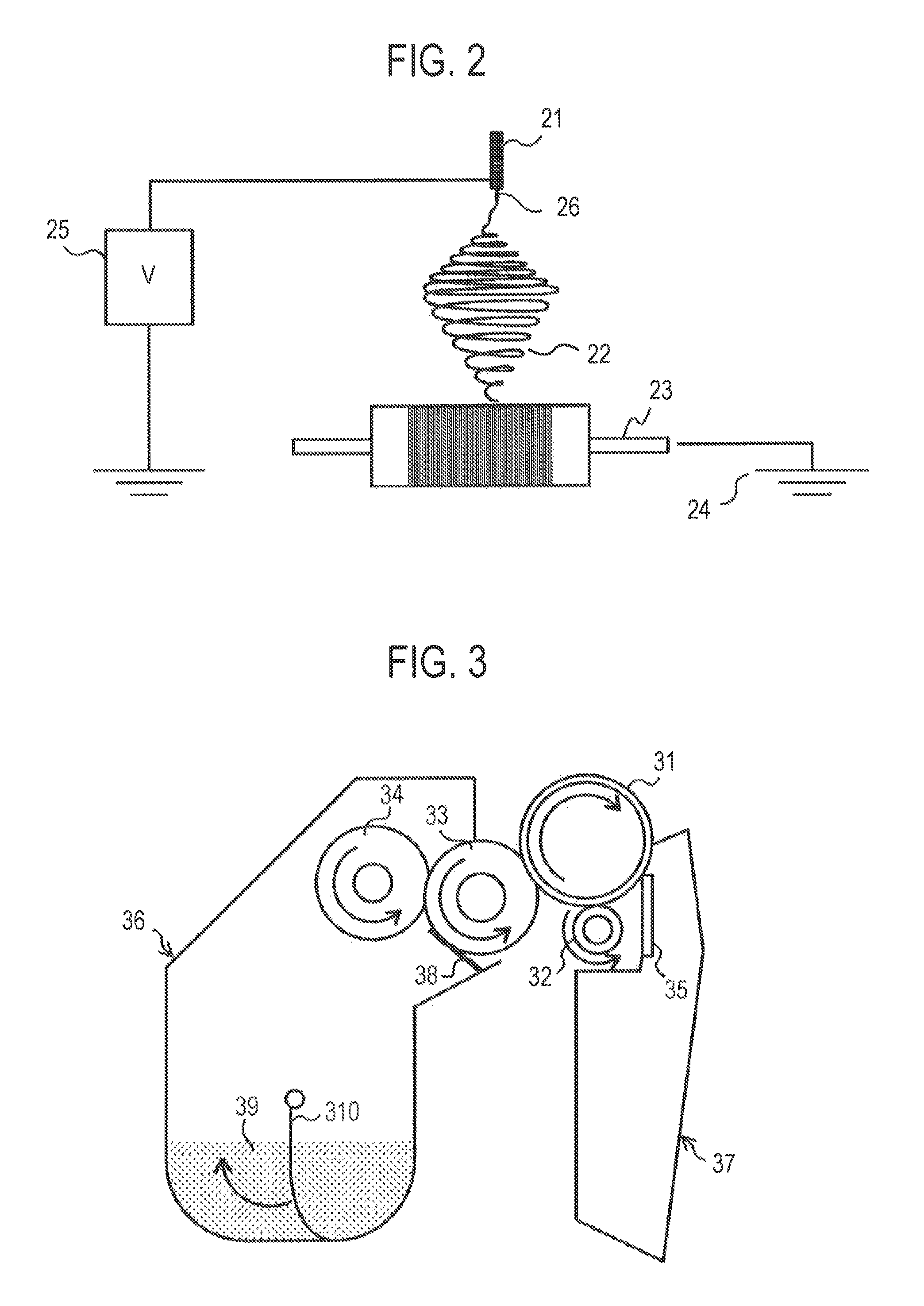

Image

  • Electroconductive member for electrophotography, process cartridge, and electrophotographic apparatus
  • Electroconductive member for electrophotography, process cartridge, and electrophotographic apparatus
  • Electroconductive member for electrophotography, process cartridge, and electrophotographic apparatus

Examples


example 1

1. Preparation of Unvulcanized Rubber Composition

[0107]An A-kneading rubber composition was obtained by mixing respective materials whose kinds and amounts were shown in Table 1 below with a pressure kneader. Further, respective materials whose kinds and amounts were shown in Table 2 below were mixed info 166 parts by mass of the A-kneading rubber composition with an open roll. Thus, an unvulcanized rubber composition was prepared.

[0108]

TABLE 1Blendingamount(part(s)Materialby mass)Raw materialNBR (trade name: Nipol100rubberDN219, manufactured byZEON CORPORATION)ElectroconductiveCarbon black40agent(trade name: TOKABLACK#7360SB, manufactured byTOKAI CARBON CO.,LTD.)FillerCalcium carbonate20(trade name: Nanox #30,manufactured by MARUOCALCIUM CO., LTD.)VulcanizationZinc oxide5accelerating aidProcessing aidStearic acid1

[0109]

TABLE 2Blendingamount(part(s)Materialby mass)CrosslinkingSulfur1.2agentVulcanizationTetrabenzyl thiuram disulfide4.5accelerator(trade name: TBZTD,manufactured by SAN...

examples 2 to 31

[0142]Electroconductive members were each produced in the same manner as in Example 1 except that; the fiber material used in the preparation of the application liquid for the layer of the network structural body was changed to a material shown in Table 4; and the conditions under which the application liquid for the layer of the network structural body was applied were changed as shown in Tables 5 to 8. Then, the members were similarly evaluated. Tables 5 to 8 show the results of the evaluations.

examples 32 to 34

[0143]Electroconductive members were each produced in the same manner as in Example 5 except that: an electroconductive elastic roller produced from an unvulcanized rubber composition obtained by mixing materials shown in Table 3 below with an open roll was used; and the injection time of the application liquid was changed, to an injection time shown in Table 8. Then, the members were similarly evaluated. Table 8 shows the results of the evaluations.

[0144]

TABLE 3Blendingamount(part(s)Materialby mass)Epichlorohydrin-ethylene oxide-allyl glycidyl ether100terpolymer (GECO) (trade name: EPICHLOMER CG-102,manufactured by DAISO CO., LTD.)Zinc oxide (ZINC OXIDE #2 manufactured by SEIDO5CHEMICAL INDUSTRY CO., LTD.)Calcium carbonate (trade name: SILVER W,35manufactured by SHIRAISHI CALCIUM KAISHA, LTD.)Carbon black (trade name: SEAST SO, manufactured by0.5TOKAI CARBON CO., LTD.)Stearic acid2Adipic acid ester (trade name: POLYCIZER W305ELS,10manufactured by DIC CORPORATION)Sulfur0.5Dipentamet...


PUM


Abstract

To suppress an image trouble resulting from abnormal discharge independent of the use conditions and use environment of an electroconductive member, provided is an electroconductive member to be used while being brought into contact with a body to be contacted, the electroconductive member comprising a layer of a network structural body on an outer peripheral surface of a electroconductive support, in which: when a surface of the network structural body in a surface of the electroconductive member is observed, at least a part of the network structural body exists in an arbitrary square region having one side length of 200 μm; the network structural body contains non-electroconductive fibers; and an average fiber diameter of a top 10% of fiber diameters of the non-electroconductive fibers measured at arbitrary points is 0.2 μm or more and 15 μm or less.

Description

CROSS-REFERENCE TO RELATED APPLICATIONS[0001]This application is a continuation of International Application No. PCT / JP2014 / 004887, filed Sep. 24, 2014, which claims the benefit of Japanese Patent Application No. 2013-202659, filed Sep. 27, 2013.BACKGROUND OF THE INVENTION[0002]Field of the Invention[0003]The present invention relates to an electroconductive member for electrophotography, a process cartridge, and an electrophotographic apparatus.[0004]Description of the Related Art[0005]In an electrophotographic apparatus as an image-forming apparatus adopting an electrophotographic system, an electroconductive member has been finding use in various applications, e.g., an electroconductive roller such as a charging roller, a developing roller, or a transfer roller. The electrical resistance value of such electroconductive roller needs to be controlled to from 103 to 1010Ω independent of its use conditions and use environment. Accordingly, the roller is provided with an electroconduc...

Claims


Application Information

Patent Timeline
Patent Type & Authority Patents(United States)
IPC IPC(8): G03G15/02G03G15/08G03G15/16
CPCG03G15/02G03G15/0233G03G15/0818G03G15/1685Y10T428/249924
Inventor YAMAUCHI, KAZUHIROYAMADA, SATORUMURANAKA, NORIFUMIKIKUCHI, YUICHIHINO, TETSUO
Owner CANON KK
Why Eureka
Try Eureka