Sliding stock for firearm

a semi-automatic firearm and stock technology, applied in the field of firearms, can solve the problems of many safety and accuracy issues of the belt loop, operator's skin burns or possibly pinches, and the operator's sleeve or skin burns, so as to achieve stable firing form and grip, and little to no loss of accuracy

Active Publication Date: 2012-05-15
SLIDE FIRE SOLUTIONS
View PDF22 Cites 27 Cited by
  • Summary
  • Abstract
  • Description
  • Claims
  • Application Information

AI Technical Summary

Benefits of technology

[0012]When properly installed, the subject invention allows the operator of a semi-automatic firearm to maintain a stable firing form and grip while rapidly re-firing their firearm with little to no loss in accuracy. In contrast to many prior art rapid-firing techniques, an operator practicing the subject method must manually push the firearm forward relative to the handle to activate the trigger following each recoil event. Therefore, each discharge event of the firearm is under the uninterrupted control of the operator's human muscle power.

Problems solved by technology

Although able to achieve a high rate of firing, the belt loop has many safety and accuracy issues.
This could lead to skin burns or possibly pinch the operator's sleeve or skin in the action.
Another issue with the belt loop method arises because the operator cannot have a firm grip on the stock or the pistol grip of the firearm.
Because of this unnatural and unbalanced firing grip, the firearm is very difficult to aim and control during the belt loop method.
However, the same safety and accuracy issues of the belt loop method apply to these devices because the firearm cannot be held securely with the trigger hand or the stock of the firearm.
One significant drawback of the Akins '918 construction is that automatic mechanisms of this type have been scrutinized for violating federal firearms laws.
Another drawback is that different spring sizes (i.e., different resistance characteristics) may be required from one unit to the next depending on the type of ammunition used so that the springs do not overpower the recoil energy.
This of course introduces inventory complexities.
One particular disadvantage of this arrangement is that the natural recoil force generated by the discharge event is compounded by the shooter's pull-stroke.
This may have a disadvantageous effect on aiming accuracy, particularly in rapid, multi-round volley shooting scenarios.

Method used


Image

  • Sliding stock for firearm
  • Sliding stock for firearm
  • Sliding stock for firearm

Examples


Embodiment Construction

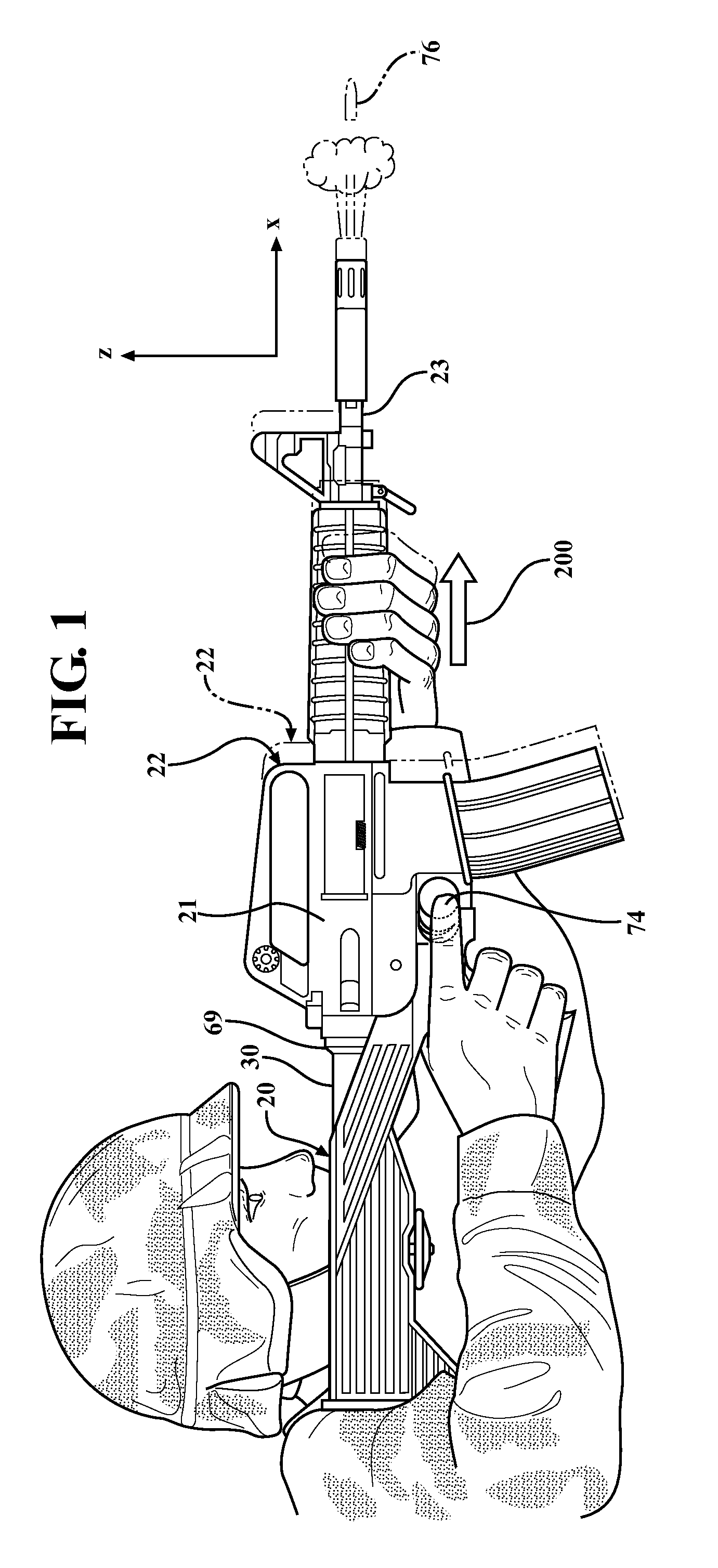
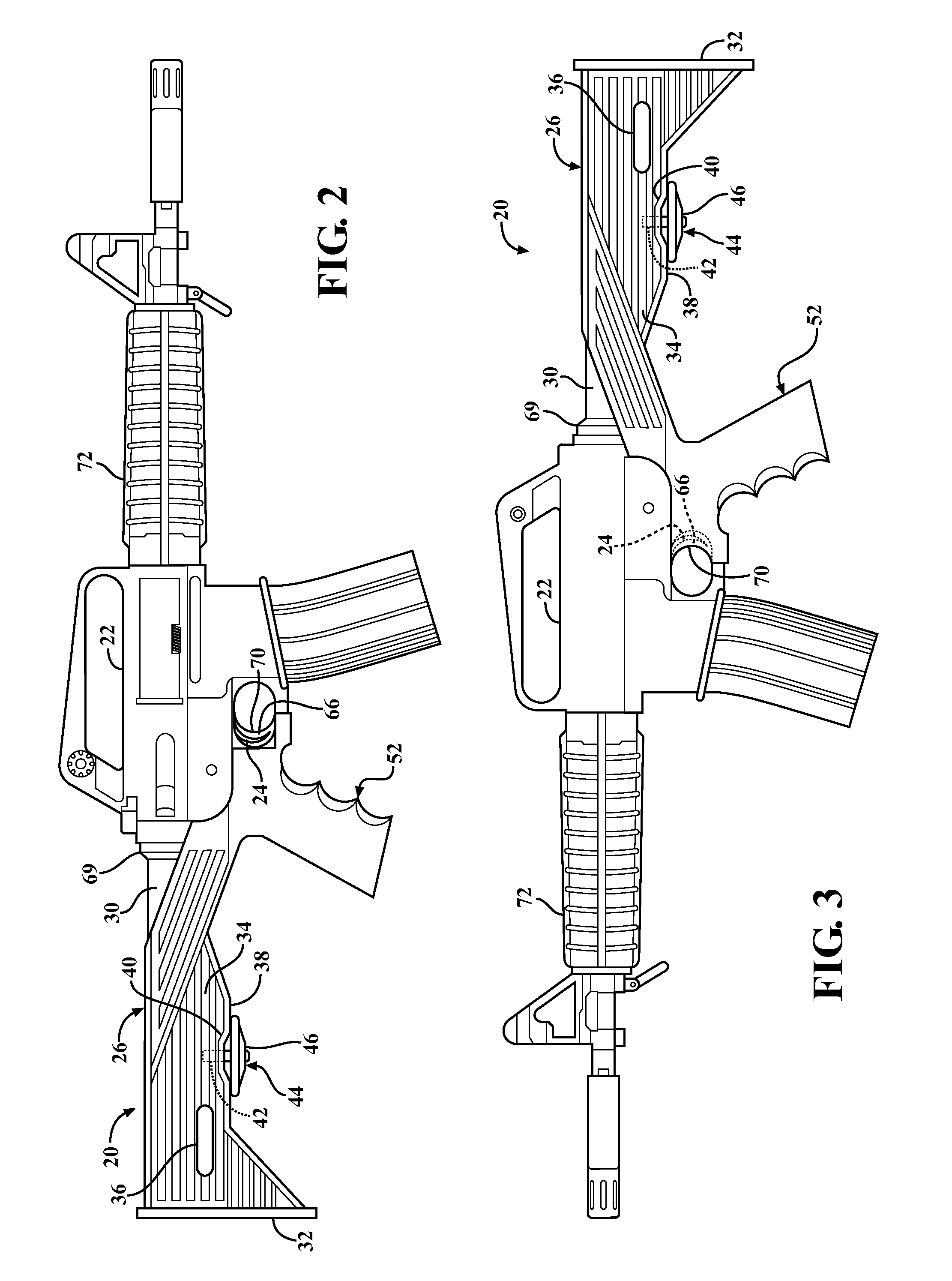
[0039]Referring to the Figures, wherein like numerals indicate like or corresponding parts throughout the several views, a serviceable firearm is shown comprising a handle 20 supported in a firing unit 22. The firing unit 22 includes a receiver 21 for chambering a round of ammunition, a barrel 23 extending forwardly from the receiver 21, and a trigger group 24 configured to selectively stimulate a round of ammunition disposed in the receiver 21. The firing unit 22 may also include additional features as will be readily understood by those of skill in the art and also as described in some details further below. The receiver 21 and barrel 23 and trigger 24 are moveable together as a firing unit 22. The handle 20 supports the firing unit 22 in use for aiming and shooting.

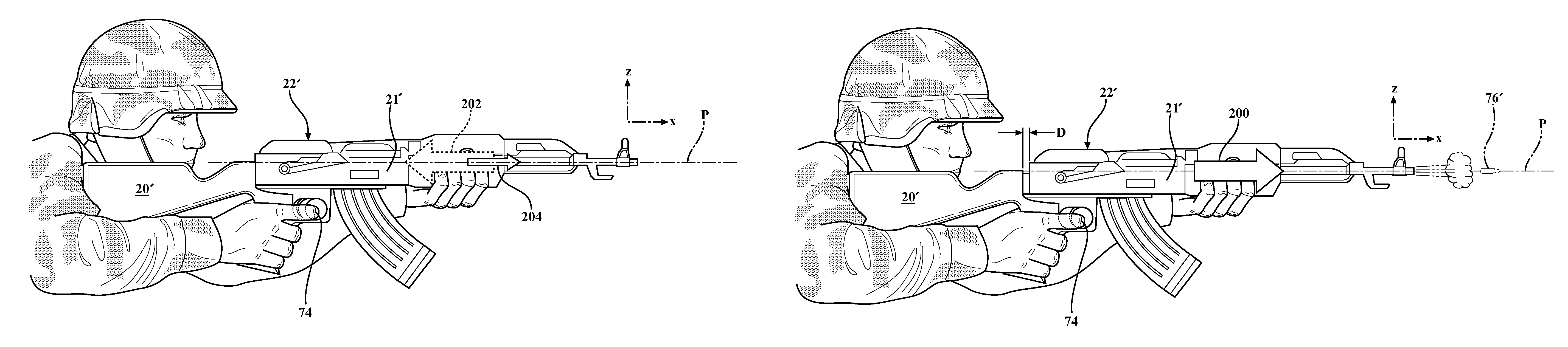
[0040]The handle 20 is shown in FIGS. 1-13 configured for attachment to an AR-15 type semi-automatic firing unit 22, as well as other firearm types model thereafter. For contrast, FIGS. 14A-19 show the handle 20′ confi...


PUM


Abstract

A handle assembly and combined interface system for use with a semi-automatic firearm to facilitate controlled bump firing methods. The handle assembly includes a finger rest for the user's trigger finger. The interface system is attached to a receiver of the firearm, and is slideably disposed in the handle assembly for reciprocation. In use, the user pushes a firing unit portion forward with an opposite hand so that its trigger collides with the user's finger, thus stimulating a round of ammunition. Recoil forces the firing unit rearwardly so that the trigger separates from the finger. The user then applies another forward activation force that urges the firing unit forwardly again to repeat the cycle for as long as the user chooses. A lock can be selectively engaged to restrict longitudinal movement of the firearm relative to the handle, thereby returning the firearm to normal semi-automatic functionality.

Description

CROSS REFERENCE TO RELATED APPLICATIONS[0001]This application is a Continuation-In-Part of U.S. Ser. No. 13 / 281,808, filed Oct. 26, 2011, which is a Continuation-In-Part of U.S. Ser. No. 12 / 949,002, filed Nov. 18, 2010, which claims the benefit of U.S. Provisional Application Ser. No. 61 / 262,315 filed Nov. 18, 2009.BACKGROUND[0002]1. Field of the Invention[0003]The present invention relates generally to firearms, and more particularly toward a sliding stock for a semi-automatic firearm configured to enable a controlled method of bump firing.[0004]2. Related Art[0005]Various techniques and devices have been developed to increase the firing rate of semi-automatic firearms. Many of these techniques and devices make use of the concept known as “bump firing”, which is the manipulation of the recoil of the firearm to rapidly activate the trigger. One such bump firing technique is known as the “belt loop” method. To execute the belt loop method, the operator first places the firearm next t...

Claims


Application Information

Patent Timeline
Patent Type & Authority Patents(United States)
IPC IPC(8): F41A19/03
CPCF41A19/11F41C23/04F41C23/14F41C23/16F41C23/20F41A19/00
Inventor COTTLE, JEREMIAH
Owner SLIDE FIRE SOLUTIONS
Why Eureka
Try Eureka