Damping force adjustment type buffer

A damping force, adjustable technology, applied in shock absorbers, shock absorbers, liquid shock absorbers, etc., can solve the problems of excessive damping force control, response delay, noise, etc., to improve the natural frequency, prevent response delay, The effect of improving responsiveness

Inactive Publication Date: 2009-10-07
HITACHI LTD
View PDF7 Cites 34 Cited by
  • Summary
  • Abstract
  • Description
  • Claims
  • Application Information

AI Technical Summary

Problems solved by technology

For example, when the damping force adjustable shock absorber is mounted on a suspension control device of a vehicle such as an automobile, and the damping force control is performed using a control signal from the controller according to the running state of the vehicle, due to the column of the pressure control valve (solenoid valve) Response delay due to inertia of the plug, etc., resulting in excessive damping force control, or noise due to self-excited vibration of the valve body of the pressure control valve

Method used


Image

  • Damping force adjustment type buffer
  • Damping force adjustment type buffer
  • Damping force adjustment type buffer

Examples


Embodiment Construction

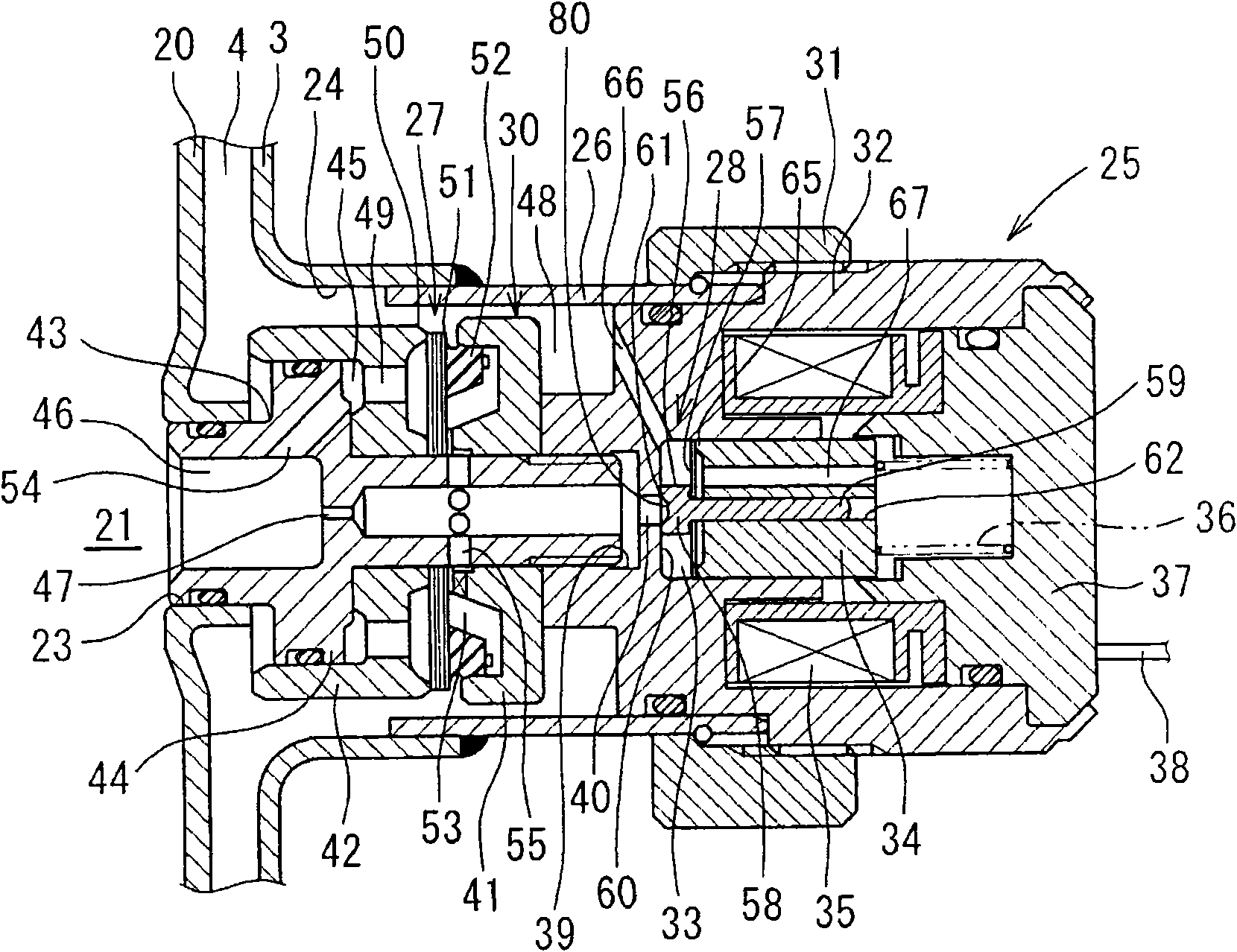
[0034] Next, a first embodiment of the present invention will be described with reference to the drawings. Such as Figure 4 As shown, the damping force adjustable hydraulic shock absorber 1 (damping force adjustable shock absorber) of this embodiment has a double-layer structure with an outer cylinder 3 on the outside of the hydraulic cylinder 2 , and between the hydraulic cylinder 2 and the outer cylinder 3 An oil storage chamber 4 is formed between them. A piston 5 is slidably embedded in the hydraulic cylinder 2, and the hydraulic cylinder 2 is divided into two chambers, a hydraulic cylinder upper chamber 2A and a hydraulic cylinder lower chamber 2B, by the piston 5 . One end of the piston rod 6 is connected with the piston 5 through the nut 7, and the other end side of the piston rod 6 passes through the upper chamber 2A of the hydraulic cylinder, passes through the guide rod 8 and the oil seal 9 installed on the upper end of the hydraulic cylinder 2 and the outer cylind...


PUM


Abstract

The invention relates to a damping force adjustment type buffer, capable of preventing the response delay of a pressure control valve and the self-excited vibration of the valve. The buffer controls the flow of the oil liquor between a ring oil line (21) and an oil storage chamber (4) generated by the slide of an inner piston of a hydraulic cylinder by a back pressure main valve (27) and a pressure control valve (28) to generate damping force. The direct damping force is generated by the pressure control valve (28) and the inner pressure of a back pressure chamber (53) is adjusted to control the valve opening pressure of the main valve 927). A valve spring (57) is mounted between a valve (56) and a plunger (34) in the pressure control valve (28) and the weight of the valve (56) is fully less than the weight of the plunger (34) and the spring rigid of the valve spring (57) is higher than the spring rigid of the plunger spring (36). Thus the response of the valve (56) is increased and the response delay of the damping force control is prevented. In addition, the natural frequency of the valve (56) is increased therefore the generation of the self-excited vibration is prevented.

Description

technical field [0001] The present invention relates to a damping force adjustable shock absorber mounted on a suspension device of a vehicle such as an automobile. Background technique [0002] The damping force adjustable shock absorber installed in the suspension device of the automobile is usually slidably embedded in the hydraulic cylinder sealed with oil, and the piston connected to the piston rod is slidably embedded, and the hydraulic cylinder is divided into two chambers. The damping force generating mechanism composed of a disc valve, etc. controls the flow of oil generated by the sliding of the piston in the hydraulic cylinder to generate damping force. The resistance changes, whereby the damping force is adjusted. [0003] As shown in Patent Document 1, a back pressure chamber is formed on the back of the disc valve, which is the damping force generating mechanism, and the back pressure chamber is connected to the hydraulic pressure on the upstream side via the ...

Claims


Application Information

Patent Timeline
Patent Type & Authority Applications(China)
IPC IPC(8): F16F9/19F16F9/34
Inventor 中楯孝雄根津隆片山洋平片山茂郎矢部博行
Owner HITACHI LTD
Why Eureka
Try Eureka