
Large channel linear guide caving transition hydraulic support
A technology of linear guidance and hydraulic support, which is applied in mine roof support, mining equipment, earthwork drilling and mining, etc., and can solve problems such as occupation, long top beam, poor stability, etc.
- Summary
- Abstract
- Description
- Claims
- Application Information
AI Technical Summary
Problems solved by technology
Method used
Image

Examples
Embodiment Construction
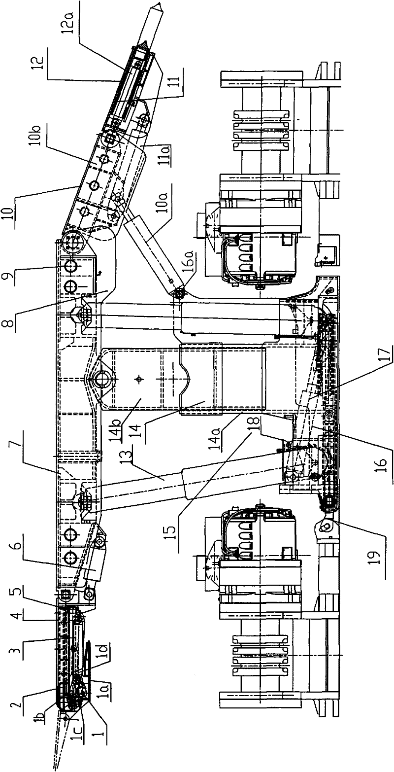
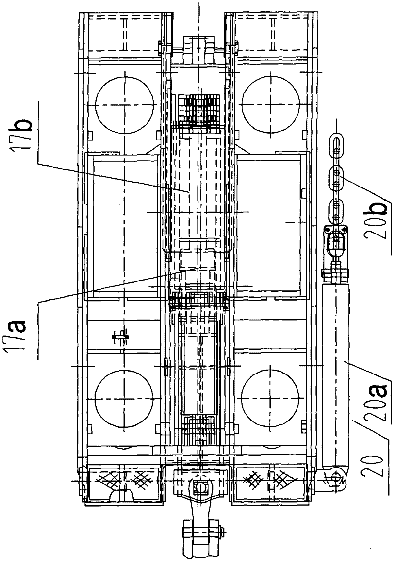
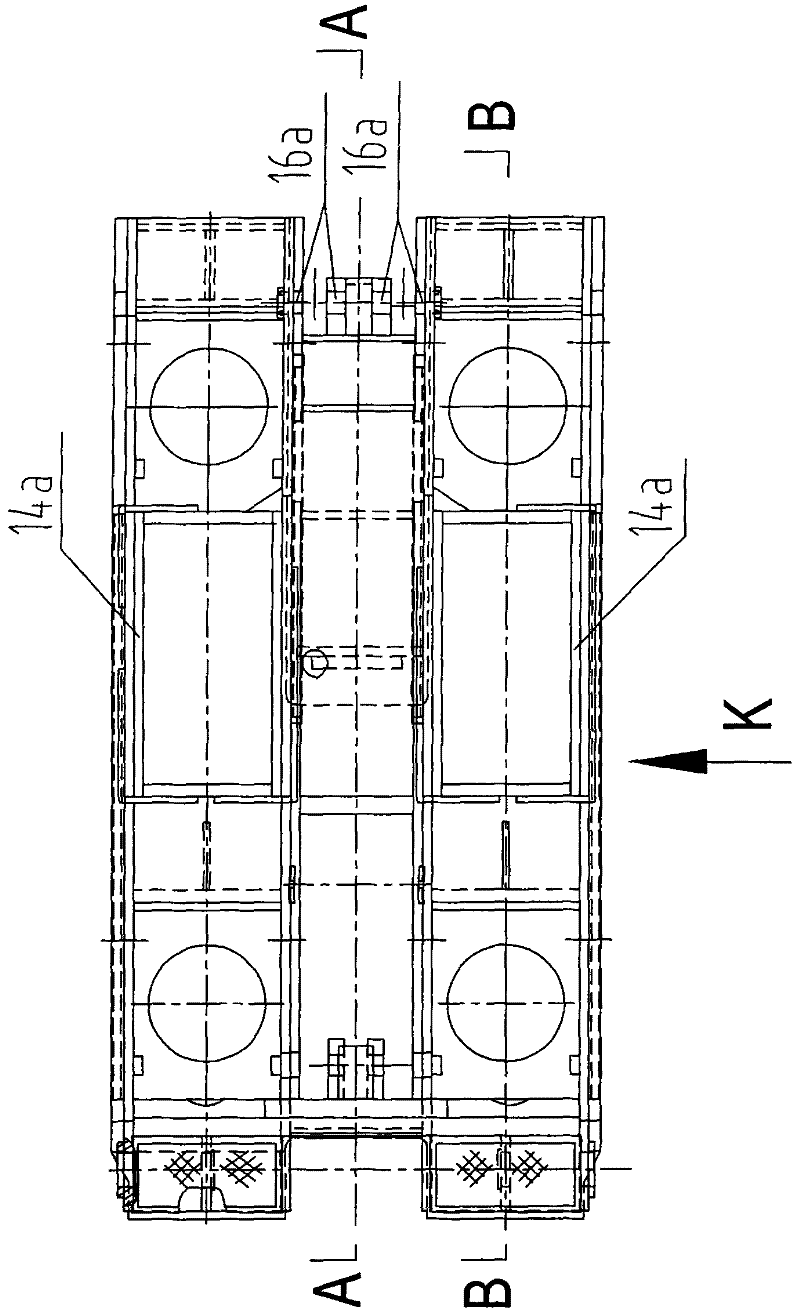
[0025] see Figure 1 to Figure 7 Shown: a large channel linear guide type top coal caving transition hydraulic support, including a column 13, the two ends of the column 13 are respectively hinged top beam 7 and base 16, the column 13 is four, symmetrical in front and rear Set, one or both sides of the top beam 7 are provided with a top beam side guard plate 8, and a side push mechanism 9 is hinged between the top beam 7 and the top beam side guard plate 8, and the side push mechanism 9 includes a side push jack 9a and The guide bar 9b is hinged to the front beam 4 at the front end of the top beam 7, the front beam jack 6 hinged between the top beam 7 and the front beam 4, the telescopic beam 2 inserted into the front beam 4, and hinged to the front beam 4 overlapped. The telescopic beam jack 3 between the supporting plate 5 and the telescopic beam 2 is hinged to the tail beam 10 at the rear end of the top beam 7. One or both sides of the tail beam 10 are provided with tail be...
PUM
 Abstract
Description
Claims
Application Information