Vertebra posterior dynamic internal rob

A fixed rod and dynamic technology, applied in the direction of internal fixator, fixator, internal bone synthesis, etc., can solve the problem of limited relative micromomentum, achieve the effect of improving dynamic stability, increasing the range of motion, and reducing the burden on the human body Effect

Inactive Publication Date: 2009-11-18
SOUTHERN MEDICAL UNIVERSITY
View PDF1 Cites 7 Cited by
  • Summary
  • Abstract
  • Description
  • Claims
  • Application Information

AI Technical Summary

Problems solved by technology

However, from accompanying drawings 11 to 13 of this patent document (see Fig.11, Fig.12 and Fig.13 of the original document), it is obvious that the rigid rod 232 is stationary relative to the sleeve 234, and only the rigid rod 230 is stationary relative to the sleeve. The barrel 234 can produce micro-movement, so the relative micro-momentum between the two rigid rods 230 and 232, that is, the relative micro-momentum between the two vertebral segments fixed with the rigid rods 230 and 232 is obviously limited

Method used


Image

  • Vertebra posterior dynamic internal rob
  • Vertebra posterior dynamic internal rob
  • Vertebra posterior dynamic internal rob

Examples


Embodiment Construction

[0024] The present invention will be described in further detail below in conjunction with accompanying drawing and specific embodiment:

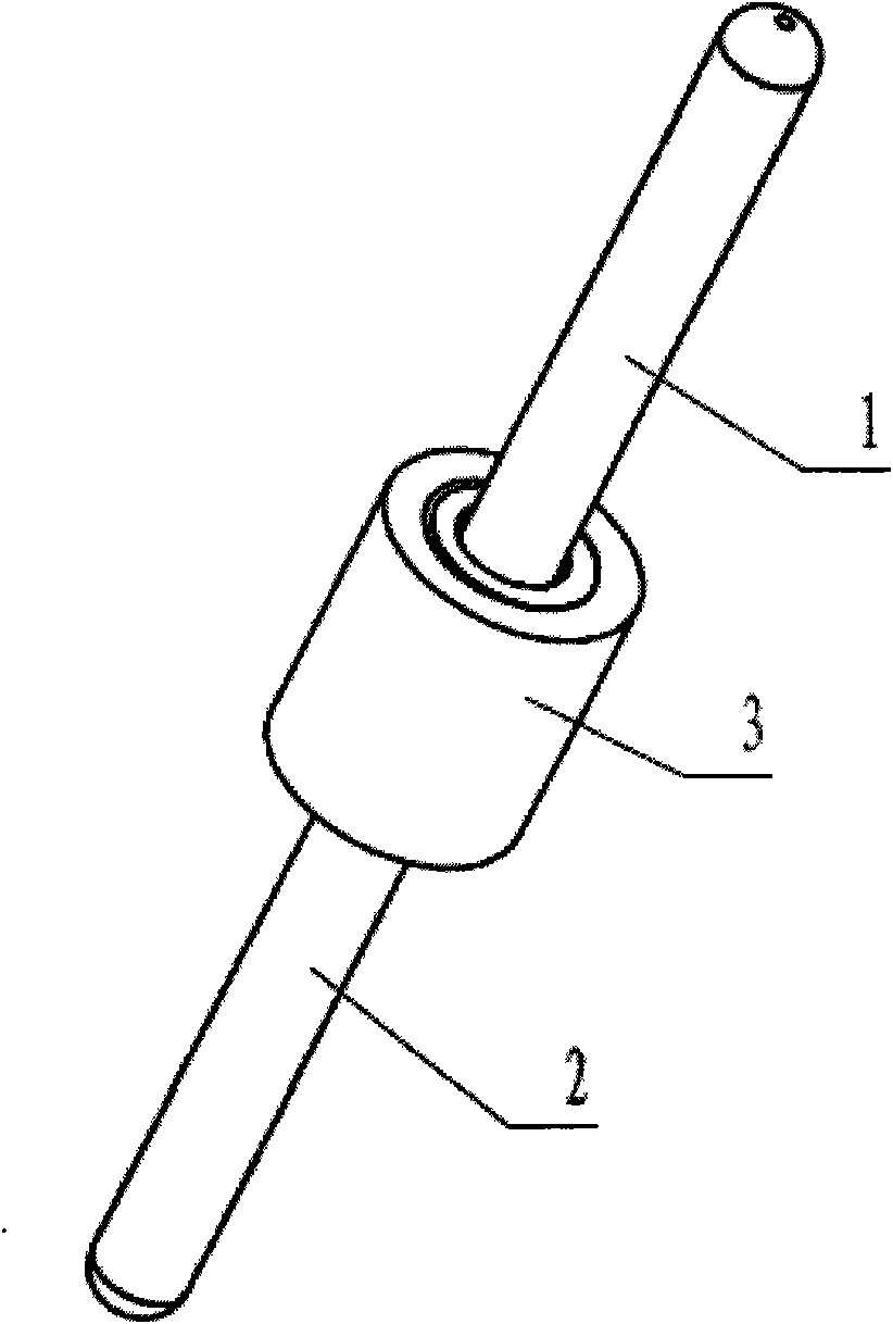
[0025] image 3 with Figure 4 It is a basic structural form of the dynamic internal fixation rod of the present invention, which consists of a first rigid rod 1, a second rigid rod 2, a sleeve 3, two screw caps 4 and eight disc springs 5, wherein the sleeve 3 is in the shape of a cylinder, and a radial barrier structure 6 is provided in the middle of the cylinder, and a screw cap 4 is threaded at both ends; the radial barrier structure 6 is annular, extending from the inner wall of the sleeve 3 to the center Extended; the center of the screw cover 4 is provided with a through hole 7; the eight disc springs 5 ​​are divided into four groups, two for each group, and each of the radial barrier structures 6 set in the sleeve 3 Two groups are respectively placed in the cavities on the side; the first rigid rod 1 and the second rigid rod 2 are ...


PUM


Abstract

The invention relates to a vertebra posterior dynamic internal rob, comprising: a first rigid rod (1) and a second rigid rod (2), which are in a head-tail connecting; a cylinder sleeve (3), a radial barrier structure(6) is arranged in the centre of the cylinder sleeve; two bind nuts (4) are separately arranged on both ends of the cylinder sleeve; wherein a through hole (7) is arranged in the centre of each bind nut (4); the first rigid rod (1) and the second rigid rod (2) are introduced to the cylinder sleeve (3) through the through hole (7); two sets of disc springs are arranged in the cavities positioned on both sides of the radial barrier structure(6) in the cylinder sleeve (3); the middle of the inner part of each rigid rod which is introduced in the sleeve (3) is expanded outward to form a flange (8) along the radial direction, each set of disc springs (5) are sheathed on each side of the flange (8), two sets of disc springs (5) are limited in the cylinder (6) which is mounted on the side of the radial barrier structure (6) by the bind nuts (4) arranged in the tail end of the cylinder sleeve (3) and the radial barrier structure (6) to resist the relative movement of the two rigid rods.

Description

Technical field: [0001] The invention relates to a medical surgical instrument, in particular to a spinal internal fixator. Background technique: [0002] The pedicle screw system is an internal fixation device commonly used in spinal surgery. It is mainly composed of pedicle screws and fixation rods. It is often used to fix the injured lumbar vertebrae to ensure the stability of the spine and the safety of the nervous system. In order to ensure the micro-movement of the fixed segment within the normal range of physiological activities and avoid complications such as adjacent segment degeneration and device fatigue fracture, dynamic internal fixation has become a research hotspot in this field. [0003] Various dynamic internal fixation rods are disclosed in the prior art, among which the representative one is the invention patent application for "Dynamic Stabilizer" published on August 14, 2008 with the publication number WO 2008 / 098206 A1, which discloses Provided a kind ...

Claims


Application Information

Patent Timeline
Patent Type & Authority Applications(China)
IPC IPC(8): A61B17/70
Inventor 唐恒涛金大地
Owner SOUTHERN MEDICAL UNIVERSITY
Why Eureka
Try Eureka