Supercharge Your Innovation With Domain-Expert AI Agents!

Push-button structure

A key and keycap technology, applied in the field of key structures with metal brackets, can solve problems such as poor structural strength and difficulty in achieving thinning

Active Publication Date: 2009-12-23
DARFON ELECTRONICS CORP
View PDF0 Cites 0 Cited by
  • Summary
  • Abstract
  • Description
  • Claims
  • Application Information

AI Technical Summary

Problems solved by technology

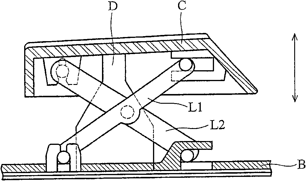
[0003] Since the traditional first and second brackets L1 and L2 are made of plastic materials, they have disadvantages such as poor structural strength and difficulty in achieving thinness; in view of this, how to design a structure with better structural strength that is conducive to thinness The optimized button structure has become an important issue

Method used


Image

  • Push-button structure
  • Push-button structure
  • Push-button structure

Examples


Embodiment Construction

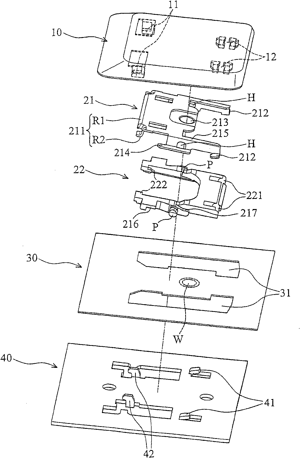
[0050] see figure 2 The button structure of an embodiment of the present invention mainly includes a keycap 10, a first bracket 21, a second bracket 22, a circuit board 30 and a bottom plate 40, the aforementioned first bracket 21 is made of metal material, the second The second bracket 22 can be made of metal or plastic material, wherein the pivot P on the first bracket 21 is movably pivotally connected to the corresponding hole H on the second bracket 22 .

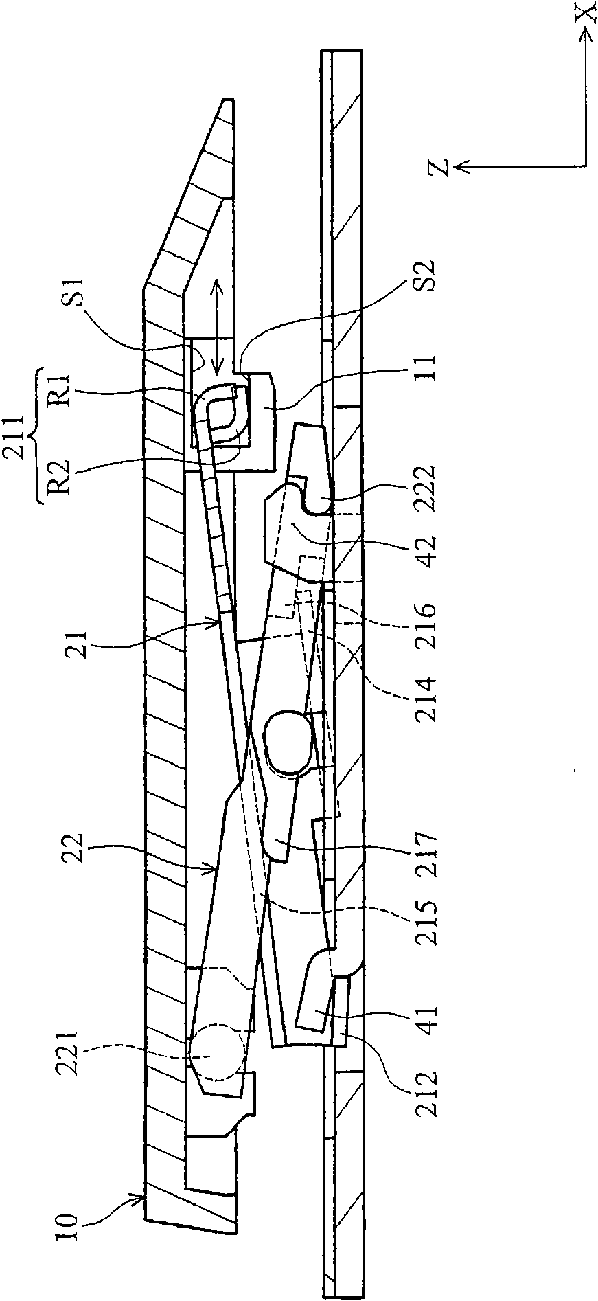
[0051] Such as figure 2 As shown, the aforementioned first and second brackets 21, 22 pass through the opening 31 on the circuit board 30 and are movably connected to the bottom plate 40 and the keycap 10, wherein the sliding end 211 on the left side of the first bracket 21 is combined with the keycap 10 In the guide groove 11, the connecting end 221 on the right side of the second bracket 22 is combined in the pivot hole 12 of the keycap 10; in addition, the connecting ends 212, 222 on the first and second brackets 2...


PUM


Abstract

The invention discloses a push-button structure comprising a bottom plate, a key cap, a first bracket and a second bracket, wherein the first bracket and the second bracket are mutually in pivot joint and are connected with the key cap and the bottom plate. The key cap is provided with a guide groove, and the guide groove approximately extends towards a first direction; and furthermore, the key cap is provided with a first bottom surface, and the guide groove is provided with a second bottom surface. The first bracket is made from metal material, wherein the first bracket is provided with a sliding end, and a first arc shape part and a second arc shape part are formed in a bending mode, are respectively abutted with the first bottom surface and the second bottom surface and can slide in the guide groove.

Description

technical field [0001] The invention relates to a key structure, in particular to a key structure with a metal bracket. Background technique [0002] See first figure 1 , an existing key structure mainly includes a bottom plate B, a key cap C, an elastic body D, a first bracket L1 and a second bracket L2, wherein the first and second brackets L1 and L2 are pivotally connected to each other, and respectively The bottom board B and the keycap C are movably connected, and the aforementioned elastic body D abuts between the bottom board B and the keycap C. The user can press the keycap C downward, and at the same time, the elastic body D can provide an upward elastic force to return the keycap C to the initial position (such as figure 1 indicated by the arrow in the middle). [0003] Since the traditional first and second brackets L1 and L2 are made of plastic materials, they have disadvantages such as poor structural strength and difficulty in achieving thinness; in view of ...

Claims


Application Information

Patent Timeline
IPC IPC(8): H01H13/12H01H13/20H01H3/12
Inventor 许建士叶亮达
Owner DARFON ELECTRONICS CORP
Features
  • R&D
  • Intellectual Property
  • Life Sciences
  • Materials
  • Tech Scout
  • Unparalleled Data Quality
  • Higher Quality Content
  • 60% Fewer Hallucinations
Learn More