Back contacted solar cell

A solar cell and back contact technology, applied in circuits, electrical components, photovoltaic power generation, etc., can solve problems such as competition, expensive solar cells, etc.

Inactive Publication Date: 2010-01-06
RENEWABLE ENERGY CORP LTD
View PDF1 Cites 20 Cited by
  • Summary
  • Abstract
  • Description
  • Claims
  • Application Information

AI Technical Summary

Problems solved by technology

However, solar cell electricity has until now been too expensive to compete with nuclear, thermal, etc.

Method used


Image

  • Back contacted solar cell

Examples


Embodiment Construction

[0023] Example of the invention

[0024] The present invention will be described by way of an example of a preferred embodiment of a method of manufacturing a back-contact type solar cell with high energy conversion efficiency and a preferred embodiment of a solar cell produced by the inventive method.

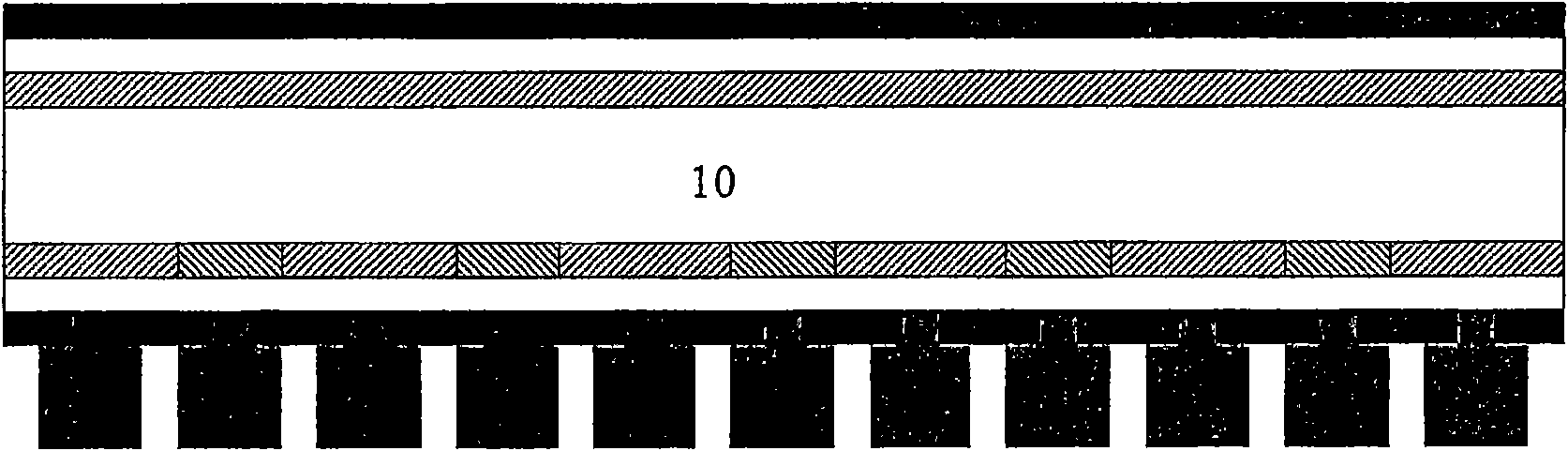
[0025] A preferred embodiment of a solar cell is shown in figure 1 middle. The silicon wafer 1 is covered on the front side by a doped layer 2 of P-type or N-type conductivity. On the back side, the silicon wafer 1 is covered by a layer 3 with alternating conductivity in an interdigitated pattern. On top of layer 2 a thin layer 4 of amorphous silicon or silicon oxide is deposited, and a layer 5 of silicon nitride is deposited on the outside of layer 4 . On the back, alternating conductive layers 3 are covered by layers 6 of amorphous silicon or amorphous silicon carbide and then by a layer 7 of silicon nitride with a doped region for each of the layers 3 at least one openi...


PUM


Abstract

This invention relates to a cost effective method of producing a back contacted silicon solar cell and the cell made by the method, where the method comprises applying a silicon substrate, wafer or thin film, doped on the back side with alternating P-type and N-type conductivity in an interdigitated pattern and optionally a layer of either P- or N-type on the front side of the wafer, depositing one or more surface passivation layers on both sides of the substrate, creating openings in the surface passivation layers on the back side of the substrate, depositing a metallic layer covering the entire back side and which fills the openings in the surface passivation layers, and creating openings in the deposited metallic layer such that electric insulated contacts with the doped regions on the back side of the substrate is obtained.

Description

technical field [0001] The present invention relates to a cost-effective method of manufacturing back-contact silicon solar cells and cells produced by the method. Background technique [0002] The world's oil supply is expected to gradually deplete over the next few decades. This means that our primary energy source of the last century will have to be replaced within a few decades to ensure current energy consumption and future increases in global energy demand. [0003] In addition, much concern has been raised that the use of fossil energy is increasing the global warming effect to such an extent that it may become dangerous. Thus, the current consumption of fossil fuels should preferably be replaced by energy sources / carriers that are renewable and sustain our climate and environment. [0004] One such source of energy is sunlight, which strikes the Earth with an energy far greater than the current and any foreseeable increase in human energy consumption. However, sol...

Claims


Application Information

Patent Timeline
Patent Type & Authority Applications(China)
IPC IPC(8): H01L31/0224
CPCY02E10/52H01L31/022425H01L31/0682H01L31/02167H01L31/022441Y02E10/547H01L31/02008H01L31/042H01L31/1804H01L31/186H01L31/202H01L31/208
Inventor 埃里克·萨乌尔安德烈亚斯·本特森
Owner RENEWABLE ENERGY CORP LTD
Why Eureka
Try Eureka