

Refrigerating device
A refrigeration device and refrigerant technology, which is applied in the direction of refrigerators, refrigeration components, refrigeration and liquefaction, etc., and can solve problems such as the decline in the cooling capacity of the evaporator
- Summary
- Abstract
- Description
- Claims
- Application Information
AI Technical Summary
Problems solved by technology
Method used
Image

Examples
no. 1 approach
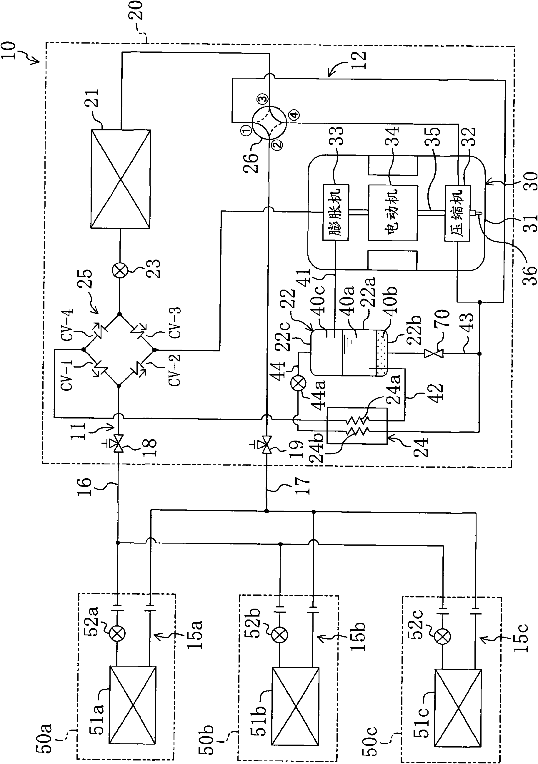
The refrigerating apparatus according to the present invention constitutes an air-conditioning apparatus 10 capable of cooling and heating indoors. Such as figure 1 As shown, the air conditioning device 10 includes an outdoor unit 20 and three indoor units 50a, 50b, and 50c. In addition, the number of indoor units 50a, 50b, and 50c is only an example, and is not limited to this.
[0082] The air conditioner 10 includes a refrigerant circuit 11. The refrigerant circuit 11 is filled with carbon dioxide (CO 2 ) As a closed circuit of refrigerant. The refrigerant circuit 11 includes an outdoor circuit 12 and three indoor circuits 15a, 15b, 15c. These indoor circuits 15a, 15b, and 15c are connected in parallel to the outdoor circuit 12 via the first connecting pipe 16 and the second connecting pipe 17. Specifically, one end of the first connecting pipe 16 is connected to the first shutoff valve 18 of the outdoor circuit 12, and the other end is divided into three branches and conne...
no. 2 approach
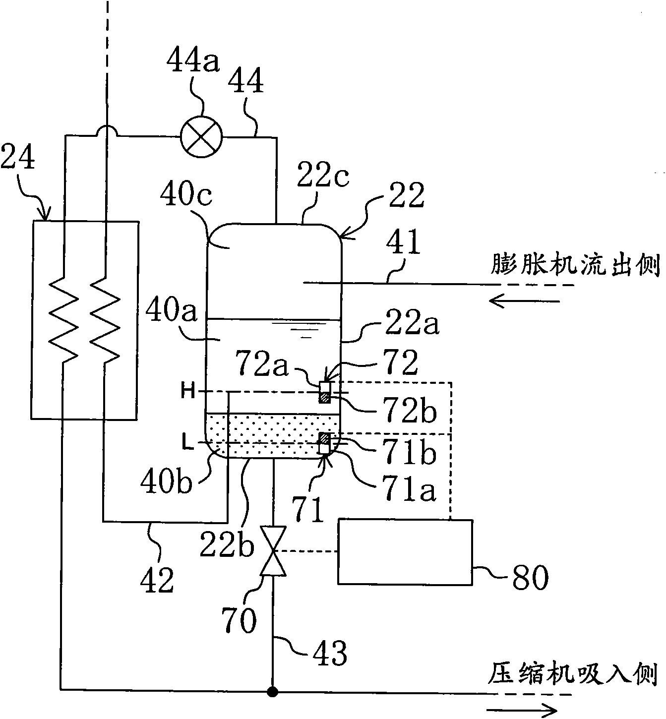
In the air conditioner 10 according to the second embodiment, the structure of the refrigerant flow restricting member is different from that of the first embodiment. Specifically, such as Figure 4 As shown, the refrigerant flow restriction member includes an on-off valve 70 as an on-off control member, a temperature sensor 73, and a control unit 80. Also, in the oil separator 22 of the second embodiment, the upper limit float switch 72 of the first embodiment is provided, but the lower limit float switch 71 of the first embodiment is not provided.
[0129] Similar to the first embodiment, the on-off valve 70 is configured to apply a predetermined resistance to the passing fluid in an open state. In other words, the on-off valve 70 doubles as a pressure reducing mechanism for reducing the pressure of the passing fluid. The temperature sensor 73 is provided on the oil delivery pipe 43 on the downstream side of the on-off valve 70. The temperature sensor 73 detects the temperatu...
no. 3 approach
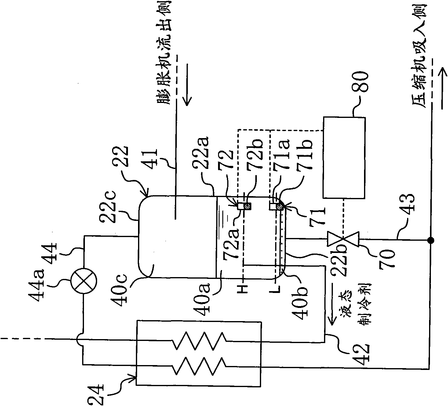
In the air conditioner 10 according to the third embodiment, the oil delivery pipe 43 of the second embodiment is provided with a heating heat exchanger 74 as a heating member. The heating heat exchanger 74 in this embodiment is provided as a pipe straddling the oil delivery pipe 43 and the inflow side of the expander 33. In the heating heat exchanger 74, the fluid flowing through the oil feed pipe 43 and the refrigerant on the inflow side of the expander 33 exchange heat. In addition, in the oil delivery pipe 43, the on-off valve 70 is provided on the upstream side of the heating heat exchanger 74, and the temperature sensor 73 is provided on the downstream side of the on-off valve 70. In this way, the on-off valve 70, the temperature sensor 73, the heating heat exchanger 74, and the control unit 80 constitute a refrigerant detection means that detects the intrusion of refrigerant from the oil separator 22 into the oil delivery pipe 43.
[0139] -The opening degree control acti...
PUM
 Abstract
Description
Claims
Application Information