
Premold housing having integrated vibration damping

A pre-formed, housing technology, applied in the direction of the measuring device housing, the components of the measuring device damping part movement, the measuring device, etc., can solve the problem of not being suitable for preventing input coupling

Inactive Publication Date: 2010-03-24
ROBERT BOSCH GMBH
View PDF0 Cites 5 Cited by
  • Summary
  • Abstract
  • Description
  • Claims
  • Application Information

AI Technical Summary

Problems solved by technology

But these known housing forms are not suitable to prevent the input coupling of disturbing acceleration

Method used


Image

  • Premold housing having integrated vibration damping
  • Premold housing having integrated vibration damping

Examples


Embodiment Construction

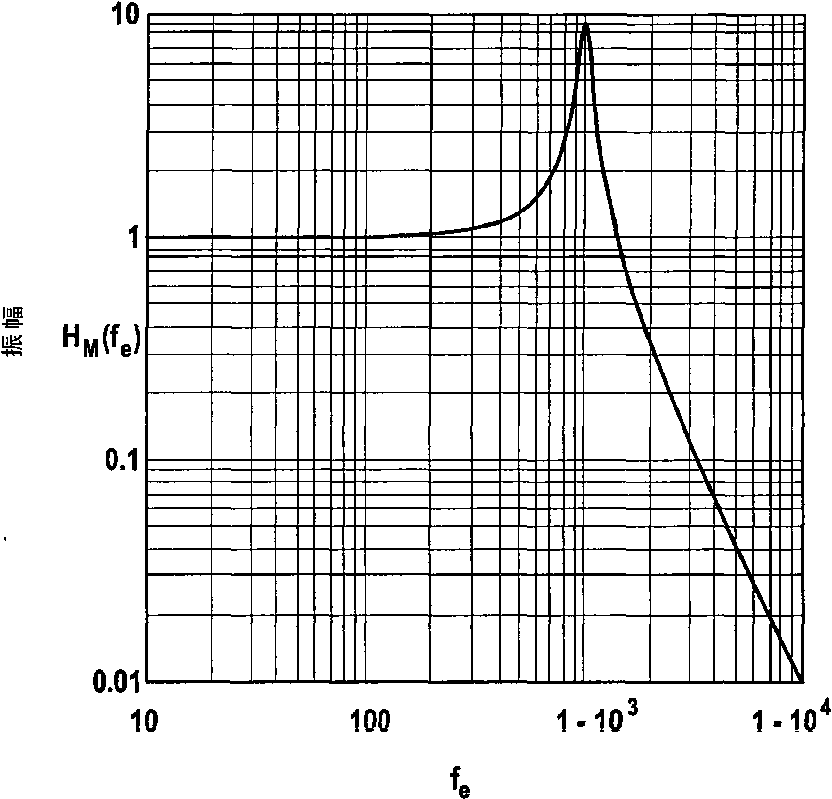
[0025] figure 1 The amplitude transfer function of the system for vibration isolation according to the invention is shown. The graph plots the ratio HM(fe) of the vibration amplitudes of the two housing parts as a function of the disturbance acceleration frequency fe measured in Hz. This value is substantially 1 in the low frequency region. This means that the coupled-in vibrations are transmitted without damping by the system. Vibration isolation does not occur because the disturbing accelerations produced by the low frequencies are too small to deform the elastically deformable medium to a noticeable extent. An increase in the frequency of the coupled-in vibrations results in a movement amplitude of the deflectable component that is actually to be protected against vibrations, ie the base plate with the chip structure, becoming greater than the amplitude of the vibration-coupled component, ie the outer housing part. The amplitude of the baseplate reaches a maximum at the ...


PUM


Abstract

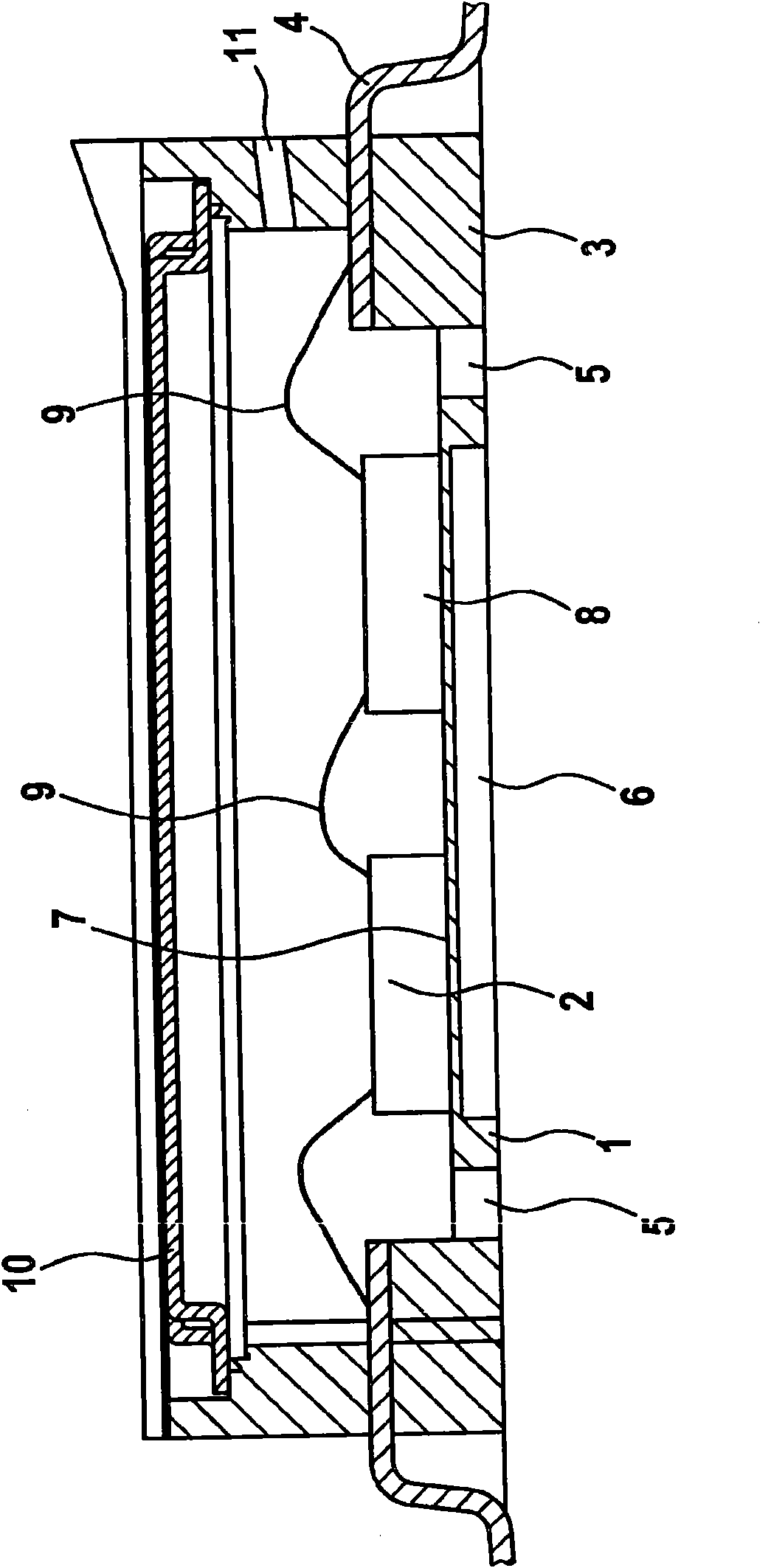
The invention relates to a premold housing for receiving a chip structure (2), in which a part (1) of the housing that is connected to the chip structure (2) is connected in an elastically deflectablemanner to another part (3) of the housing that is attached to a supporting structure carrying the entire housing, the two housing parts (1, 3) not coming in contact with each other.

Description

technical field [0001] The invention relates to a preformed housing for accommodating chip structures, in particular micromechanical sensors, with vibration isolation integrated in the housing. Background technique [0002] Micromechanical inertial sensors for measuring rotational speed or acceleration are now durable components of active or passive safety systems in vehicles. Airbags and driving dynamics adjustment are typical examples of other systems. Functional failures due to incorrect interpretation of sensor signals have a major impact on safety in these systems. [0003] In particular micromechanical sensors for various acceleration and movement measurements must be protected against disturbing accelerations against damage or malfunction. Interference accelerations of this type can act on the individual sensors, in particular via vibrations coupled in via an insufficiently damped support structure. [0004] The undesired coupling of vibrations is particularly prob...

Claims


Application Information

Patent Timeline
Patent Type & Authority Applications(China)
IPC IPC(8): B81B7/00G01D11/24G01P1/02
CPCG01D11/245B81B2201/0242G01D11/10B81B7/0058B81B2203/053G01P1/023H01L2924/0002H01L2924/00
Inventor K·因格里施E·伊利克M·阿本德罗特
Owner ROBERT BOSCH GMBH
Learn More