Blade of vertical axis wind turbine

A wind power generator, vertical axis technology, applied to wind power generators, wind power generators at right angles to the wind direction, engines, etc., can solve the problem of closed airfoil blades with small sweeping area, slow start speed, and affecting the start wind speed of the wind rotor And other issues

Inactive Publication Date: 2010-05-19
深圳风光新能源有限公司
View PDF0 Cites 1 Cited by
  • Summary
  • Abstract
  • Description
  • Claims
  • Application Information

AI Technical Summary

Problems solved by technology

The blades currently used are closed airfoils, the blade cross section is streamlined, symmetrical up and down on the horizontal line, the resistance is large, the starting speed is slow, and the aerodynamic efficiency is low
[0005] To sum up, the existing vertical wind power generators still have certain disadvantages when they are in use. Since the blades of the existing vertical wind power generators are closed airfoil blades, when the blades are exposed to wind, their closed The airfoil blades and sweeping area are small, which affects the starting wind speed of the connected wind rotor and the efficiency of converting wind energy. This is a major shortcoming of the existing vertical wind turbine blades
[0006] And because the existing vertical wind power generator blades are closed airfoil structures, when there is a transverse wind acting on the closed airfoil blades, the wind will do laminar flow motion on the closed airfoil blades, resulting in closed airfoil The blades of the type structure have very little resistance to the wind, which reduces the force of the wind acting on the closed airfoil blade and reduces the force of the closed airfoil blade on the wind wheel, thereby reducing the working efficiency of the wind wheel. This is Yet another disadvantage of existing blades

Method used


Image

  • Blade of vertical axis wind turbine
  • Blade of vertical axis wind turbine
  • Blade of vertical axis wind turbine

Examples


Embodiment Construction

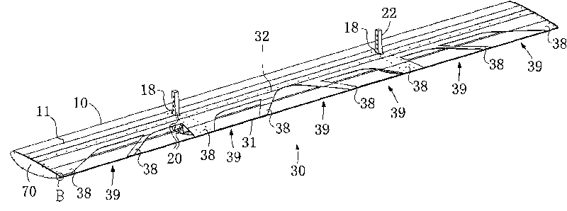
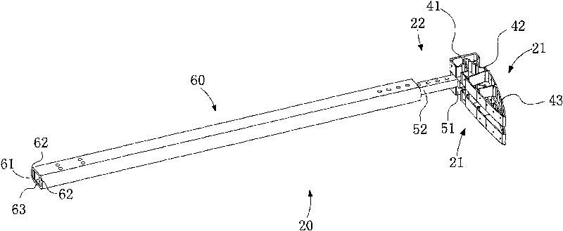
[0028] Such as Figure 1-9 Shown: a blade of a vertical axis wind power generator, which includes a shell unit 10, a blade support unit 20 and a wind hunting unit 30, wherein the shell unit 10 includes a first shell baffle 11, a second shell baffle Plate 12 and reinforcement baffle 13.

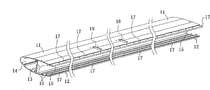
[0029] Such as figure 1 , 2 As shown: one side of the first casing baffle 11 is fixedly connected to one side of the second casing baffle 12, and the reinforcing baffle 13 is fixedly connected to the first casing baffle 11 and the second casing Between the baffles 12, a cavity 14 and a snap-in groove 15 are formed. The cavity 14 is arranged near the side where the first housing baffle 11 and the second housing baffle 12 are connected, and the cavity The two ends of body 14 are connected.

[0030] The clamping groove body 15 is arranged on the other side of the cavity body 14, the groove wall of the clamping groove body 15 is formed by the first housing baffle plate 11 and the second housin...


PUM


Abstract

The invention relates to a blade of a vertical axis wind turbine, which comprises a blade housing unit, a blade supporting unit and a blade wind catching unit, wherein the blade wind catching unit is fixedly connected with the blade supporting unit and the blade housing unit; with the help of a plurality of wind catching ports of the wind catching unit, wind can enter into a cavity of the blade from a plurality of wind catching ports under the action of the wind, thereby leading the wind to be simultaneously acted on the outer surface of the wind catching unit and on the inner surface of the wind catching unit and further increasing the wind sweeping area of the blade; furthermore, when in existence of the transverse sweeping wind, the wind carries out the turbulent motion on the blade, thereby further increasing the rotational speed of the blade, improving the energy conversion efficiency of a wind turbine and improving the efficiency of the wind turbine under the premise of not changing the original external shape of the blade.

Description

technical field [0001] The invention relates to a blade of a wind power generator, in particular to a blade of a vertical axis wind power generator. Background technique [0002] Wind power generation is an energy conversion device that converts wind energy into mechanical energy, electrical energy or thermal energy. Wind power generation was originally an environmentally friendly power generation device developed to solve emergency power supply and power supply in remote areas. However, with the rapid development of science and technology Development and population growth have brought energy crisis to the world, so countries all over the world are developing wind power as a supplementary energy source. [0003] However, the initial wind turbines had high requirements for starting wind speed and high power generation noise, so wind turbines could only be placed in inaccessible or windy places. Equipment is also developing in the direction of large institutions, and large wi...

Claims


Application Information

Patent Timeline
Patent Type & Authority Applications(China)
IPC IPC(8): F03D3/06
CPCY02E10/74
Inventor 王光明
Owner 深圳风光新能源有限公司
Why Eureka
Try Eureka