System for managing a reagent dispensing device in an exhaust line

A technology for exhaust pipelines and reactants, which can be used in exhaust treatment, electronic control of exhaust treatment devices, transmission systems, etc., and can solve problems such as changes

Inactive Publication Date: 2010-07-21
PEZHO SITROEN AUTOMOBILS SA
View PDF0 Cites 1 Cited by
  • Summary
  • Abstract
  • Description
  • Claims
  • Application Information

AI Technical Summary

Problems solved by technology

Thus, the concept implies the development of a specific control unit for controlling the injection of reactants, which in addition to the specific control unit development costs also entails assembly costs and wiring costs for easy access to this specific control unit, in some cases at least with The cost of changing the body, compartment or other parts of the car, its positioning, etc.

Method used


Image

  • System for managing a reagent dispensing device in an exhaust line
  • System for managing a reagent dispensing device in an exhaust line

Examples


Embodiment Construction

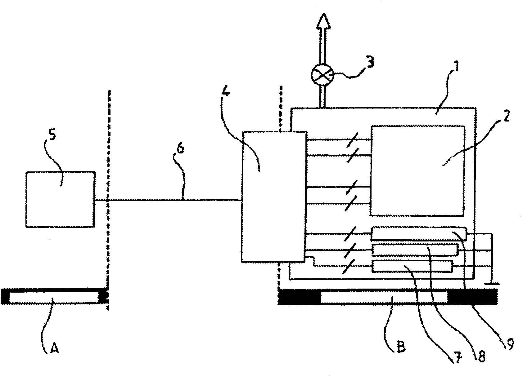
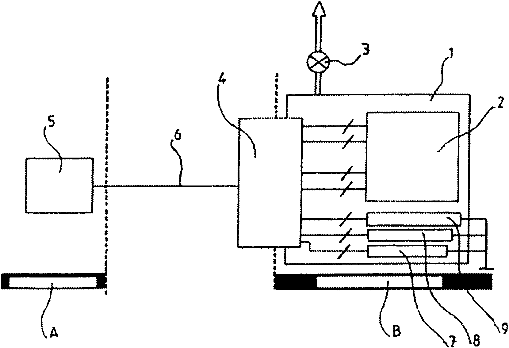
[0030] The distribution circuit comprises a container 1 for quantitatively injecting reactants into the exhaust gas. For the catalytic reduction of NOx with the SCR, the container has a volume of about 25 liters, about the volume of a wheel, and is located away from the underhood area (engine compartment), for example, near the trunk or in zone B therein.

[0031] This distribution circuit comprises injection means 3 capable of extracting a quantity of reactant in container 1 and injecting it into the exhaust gas. For this purpose, the injection device 3 comprises, for example, a metering pump, controlled according to the pressure demand in the injection circuit; and nozzles, which inject the required amount of reactant. exist figure 1 In , the sending of a portion of the reactants to the point where they are injected into the exhaust is indicated by the arrow symbol from pump 3 .

[0032] As mentioned above, the reactant is based on urea which freezes at -11°C, so the distr...


PUM


Abstract

The invention relates to a system for managing a reagent dispensing device in the exhaust line of an engine, said circuit including a tank (1), an injection means (3), a means for conditioning the reagent, sensors capable of determining the representative parameters of the condition of the dispensing circuit and of the reagent, and actuators for controlling the conditioning and injection means driven by a calculation unit based on the condition of the dispensing circuit and of the reagent and on the engine parameters determined by an engine control unit (5) characterised in that the calculation unit is integrated in the engine control unit (5) and in that the system includes an analog / digital interface (4) for processing the analog signals from the sensors (2) and the actuators (3, 7, 8, 9), provided in the vicinity of the tank (1) and connected to the engine control unit by a multiplexed digital link.

Description

technical field [0001] This application claims priority from French patent application 0756936 filed on August 3, 2007, the content of which (description, claims and drawings) is incorporated herein by reference. [0002] The invention relates to the control of reactant distribution circuits in exhaust lines. Background technique [0003] The pollutants produced by the combustion of automobile engines, diesel engines or gasoline engines are mostly unburned hydrocarbons HC, nitrogen oxides (one nitrogen oxide NO and two nitrogen oxides NO 2 , generally collectively referred to as NOx), carbon oxides (monocarbon oxide CO) and solid particles of carbon in the case of lean-burn diesel engines and direct-injection gasoline engines. [0004] Direct injection of hydrocarbon fuels and systems that partially reintroduce exhaust gases into the engine can reduce the formation of certain pollutants in the same combustion chamber, but in order to meet increasingly stringent environmenta...

Claims


Application Information

Patent Timeline
Patent Type & Authority Applications(China)
IPC IPC(8): F01N3/20F01N9/00
CPCF02D41/266F01N2900/1811F01N2610/146Y02T10/24H04L2012/40215F01N2610/1406H04L2012/40273F01N3/208F01N2610/02Y02A50/20Y02T10/12
Inventor A·萨格X·赛迪洛特
Owner PEZHO SITROEN AUTOMOBILS SA
Why Eureka
Try Eureka