Pedal bottom plate structure

A base plate and pedal technology, applied in the direction of pedals, bicycle accessories, bicycle racks, etc., can solve the problems of complicated and troublesome installation operations, achieve the effect of improved appearance, reduced number of parts, and good foot clamping

Inactive Publication Date: 2010-10-06
HONDA MOTOR CO LTD
View PDF3 Cites 8 Cited by
  • Summary
  • Abstract
  • Description
  • Claims
  • Application Information

AI Technical Summary

Problems solved by technology

[0004] The above-mentioned opening is a hole with a closed edge, so when installing the foot pedal base plate to the vehicle body on which the foot brake pedal is installed, it is necessary to drill the tread portion of the foot brake pedal through the opening, and the installation work is complicated.
[0005] In addition, since the opening is larger than the tread portion, it is troublesome to take into account appearance issues such as concealment by the floor mat.

Method used


Image

  • Pedal bottom plate structure
  • Pedal bottom plate structure
  • Pedal bottom plate structure

Examples


Embodiment Construction

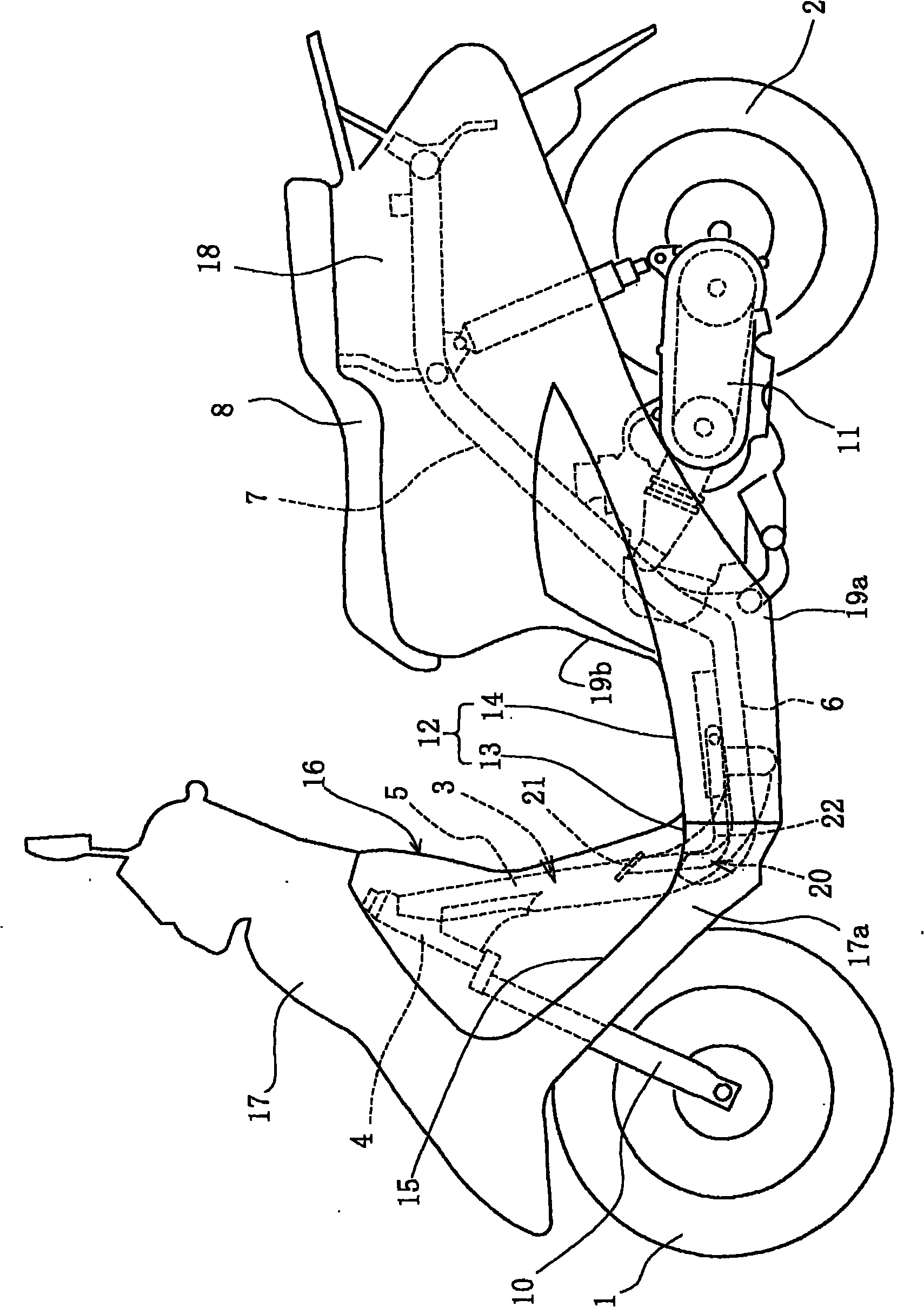
[0030] Embodiments will be described below based on the drawings. figure 1 It is a side view of a scooter-type two-wheeled vehicle to which the present invention is applied. The body frame 3 for supporting the front wheel 1 and the rear wheel 2 of the motorcycle has a steering riser 4 at the front end, and has: a main pipe 5 inclined backward from the steering riser 4 and extending downward; A bottom pipe 6 extending substantially horizontally rearward from a lower portion of the main pipe 5 , and a rear pipe 7 integrally extending backward from the bottom pipe 6 slanting upward. The rear pipe 7 supports a seat 8 arranged above.

[0031] A steering shaft (not shown) integrated with a front fork 10 is rotatably supported on the steering stem 4 , and the lower end of the front fork 10 supports the front wheel 1 .

[0032] A swing type power unit 11 integrated with the rear wheel 2 is supported swingably at the lower portion of the rear pipe 7 .

[0033] Above the bottom pipe ...


PUM


Abstract

The invention provides a pedal bottom plate structure, which has a pedal through hole for operating the pedal with a good installation structure, a good appearance and a small area. The pedal bottom plate (12) is divided into a first bottom plate portion (13) and a second bottom plate portion (14) in the back and forth direction. The first bottom plate portion (13) is formed with a groove which is embedded in an approximately U shape from a seam (30) to forward. The thickness of the groove is as wide as that of the arm portion (22) and is smaller than the pedal portion (21). When the first bottom plate portion (13) and the second bottom plate portion (14) are connected, the seam (30) side is sealed to form the pedal through hole (23).

Description

technical field [0001] The present invention relates to a pedal floor structure of a motorcycle, etc., and particularly relates to a pedal floor structure effective for a scooter-type motorcycle, etc., having a pedal floor provided with a pedal of a brake or the like . Background technique [0002] There is known a structure in which an opening is provided on the pedal floor of a scooter-type motorcycle, and the foot brake pedal protrudes upward from the opening. [0003] Patent Document 1: Japanese Patent No. 3515776 [0004] The above-mentioned opening is a hole with closed edges. Therefore, when the foot pedal base plate is installed on the vehicle body on which the foot brake pedal is installed, it is necessary to drill the tread portion of the foot brake pedal through the opening, which complicates the installation work. [0005] In addition, since the opening is larger than the tread portion, it is necessary to consider an appearance problem such as concealment by th...

Claims


Application Information

Patent Timeline
Patent Type & Authority Applications(China)
IPC IPC(8): B62J25/00B62L3/04B62K19/38
Inventor 王叶廖长亮康明闯
Owner HONDA MOTOR CO LTD
Why Eureka
Try Eureka