Drip-proof throttling nozzle device and usage thereof

A nozzle device and anti-drip technology, which is applied in the direction of spraying devices, spraying devices, etc., can solve the problems of railway transportation safety hazards, waste of residual liquid resources, increased labor workload of workers, etc.

Active Publication Date: 2010-12-08
TAIYUAN UNIV OF TECH
View PDF6 Cites 8 Cited by
  • Summary
  • Abstract
  • Description
  • Claims
  • Application Information

AI Technical Summary

Problems solved by technology

For example, in the antifreeze spraying device of the train, on the one hand, the remaining liquid will flow to the joint of the train car, because the antifreeze has a certain corrosiveness, so it will cause corrosion to the joint of the train car, thereby affecting the railway. Transportation brings certain potential safety hazards; on the other hand, the residual liquid will flow to the ground of the coal mine transportation and sales station, which not only easily causes corrosion to the rails, but also increases the labor workload for the workers for the cleaning work; in addition, the residual liquid Not controlling is also a waste of resources
[0004] (2) When the pressure in the liquid delivery pipeline in the liquid spraying device is constant, the nozzle can only spray at a constant flow rate
For example, in the antifreeze spraying device of trains, the amount of antifreeze sprayed per ton of coal has a great relationship with the temperature. When the temperature is low, it is necessary to increase the amount of antifreeze sprayed per ton of coal. Coal antifreeze spraying amount, the nozzles in the antifreeze spraying device currently used cannot adjust the flow rate of antifreeze spraying
[0005] (3) At present, the spraying effect of the nozzle still has a large gap with the ideal requirements in many aspects such as the uniformity after spraying and the coverage area.

Method used


Image

  • Drip-proof throttling nozzle device and usage thereof
  • Drip-proof throttling nozzle device and usage thereof
  • Drip-proof throttling nozzle device and usage thereof

Examples


Embodiment Construction

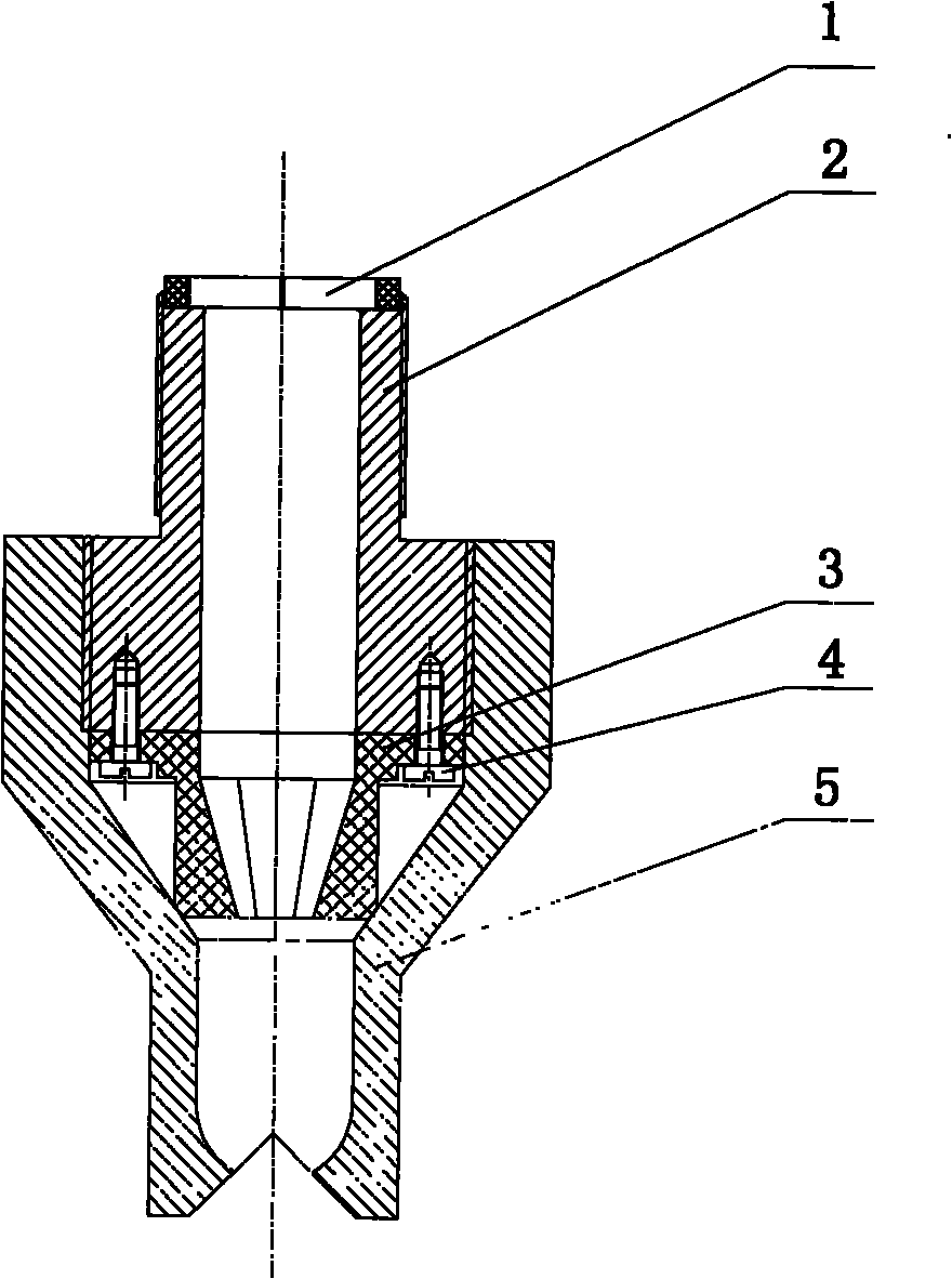
[0026] A drip-proof and throttling nozzle device of the present invention and its application method in conjunction with its application in train antifreeze spraying devices will be further described in detail below in conjunction with the accompanying drawings.

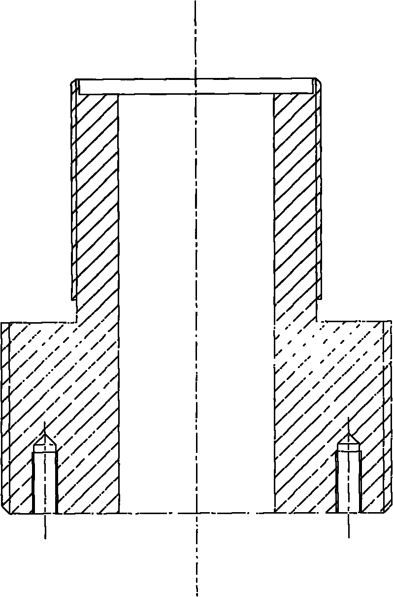
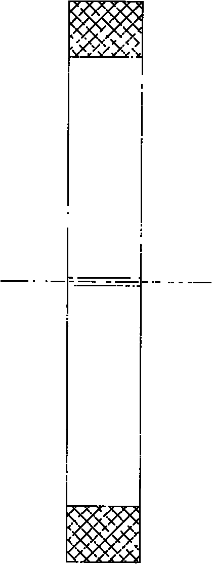
[0027] Such as figure 1 As shown, a drip-proof and throttling nozzle device of the present invention is composed of a gap diaphragm 1, a nozzle top core 2, a nozzle bottom core 3, a slotted pan head screw 4 and a nozzle cover 5. The gap diaphragm is placed in the circular groove on the upper end surface of the nozzle top core 2; the outer part of the nozzle top core 2 has metric threads at both ends on the two cylindrical surfaces with different radii, and the metric thread on the cylindrical surface with the smaller radius The thread is used for the connection between the nozzle top core 2 and the antifreeze liquid delivery pipeline, and the metric thread on the cylindrical surface with a larger radius is used for t...


PUM


Abstract

The invention relates to a drip-proof throttling nozzle device and a usage thereof, which belong to the field of mechanic design, in particular to a drip-proof throttling nozzle device which effectively prevents residual liquid flows down in a large amount after spraying liquid on the nozzle and adjusts the flow of liquid and a technical scheme of the usage. The drip-proof throttling nozzle device consists of a gap membrane, a nozzle top core, a nozzle bottom core, a slotted pan head screw and a nozzle outer cover. In the invention, the nozzle is provided with a gap membrane assembly and a nozzle bottom core assembly and the two and other assemblies of the nozzle and related assembling relationship are arranged so that drip-proofing and adjustment of flow are realized when the nozzle sprays, deficiency that the residual liquid flows down in a large amount after spraying liquid on the nozzle is overcome and the flow of liquid flowing through is controlled by adjusting the nozzle. And the opening form of the nozzle is designed so that the liquid sprayed is in form of a fan to improve the spraying uniformity and covering area.

Description

technical field [0001] The invention relates to an anti-drip and throttling nozzle device and its use method, belonging to the field of mechanical design, and in particular to an anti-dripping device that effectively prevents a large amount of residual liquid from flowing down after the nozzle sprays liquid and realizes that the nozzle can adjust the flow of liquid passing through it. A dripping and throttling nozzle device and a technical proposal of a using method thereof. Background technique [0002] As a very important part of the liquid spraying device, the nozzle is widely used in many fields such as mining, metallurgy, chemical industry, automobile, electronics, agriculture, papermaking, printing, environmental protection, power generation, water treatment and precision machinery. In modern production practice, the requirements for the use of nozzles are getting higher and higher. It is not only required to shorten the follow-up cleaning tasks of workers after sprayi...

Claims


Application Information

Patent Timeline
Patent Type & Authority Applications(China)
IPC IPC(8): B05B1/02B05B1/28B05B1/30
Inventor 牛志刚刘晓恒
Owner TAIYUAN UNIV OF TECH
Why Eureka
Try Eureka