Temperature measuring type electrical fire monitoring system

A technology of electrical fire and monitoring system, which is applied in the direction of electric fire alarm, measurement of electric variables, measurement of current/voltage, etc., to prevent accidents and eliminate electrical hidden dangers

Active Publication Date: 2011-02-02
陕西银河电力仪表股份有限公司
View PDF5 Cites 12 Cited by
  • Summary
  • Abstract
  • Description
  • Claims
  • Application Information

AI Technical Summary

Problems solved by technology

At this time, the electric spark released can easily ignite the surrounding combustibles and combustibles, thus causing a fire accident.

Method used


Image

  • Temperature measuring type electrical fire monitoring system
  • Temperature measuring type electrical fire monitoring system
  • Temperature measuring type electrical fire monitoring system

Examples


Embodiment Construction

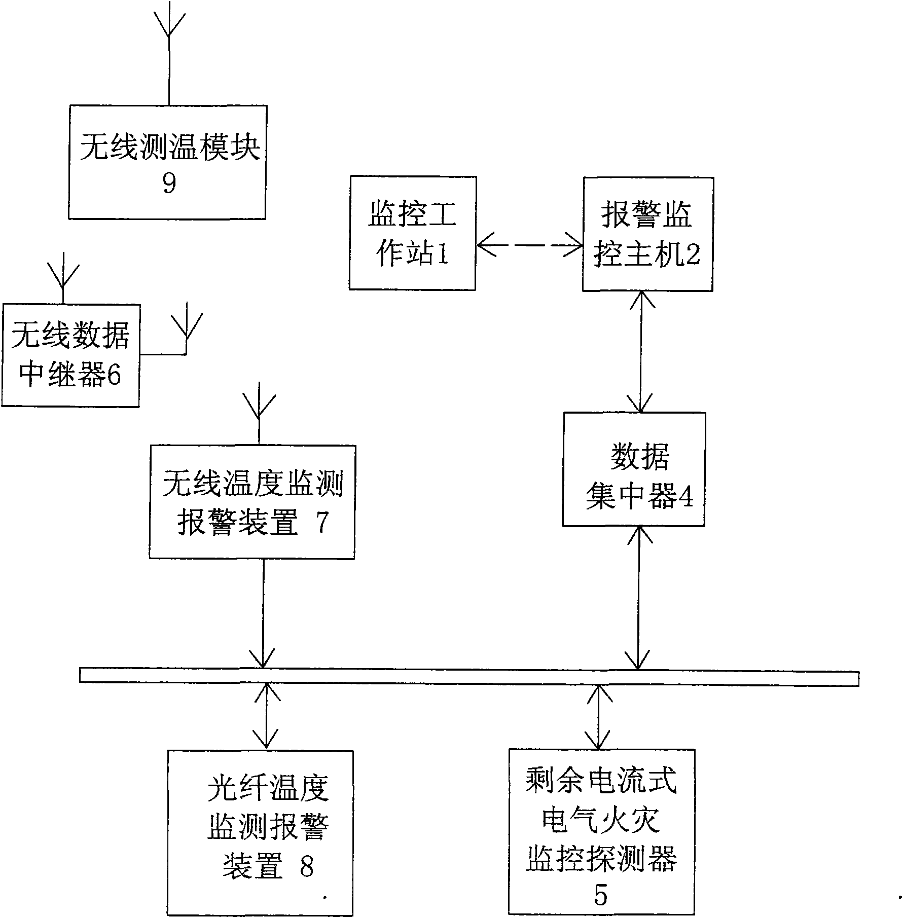
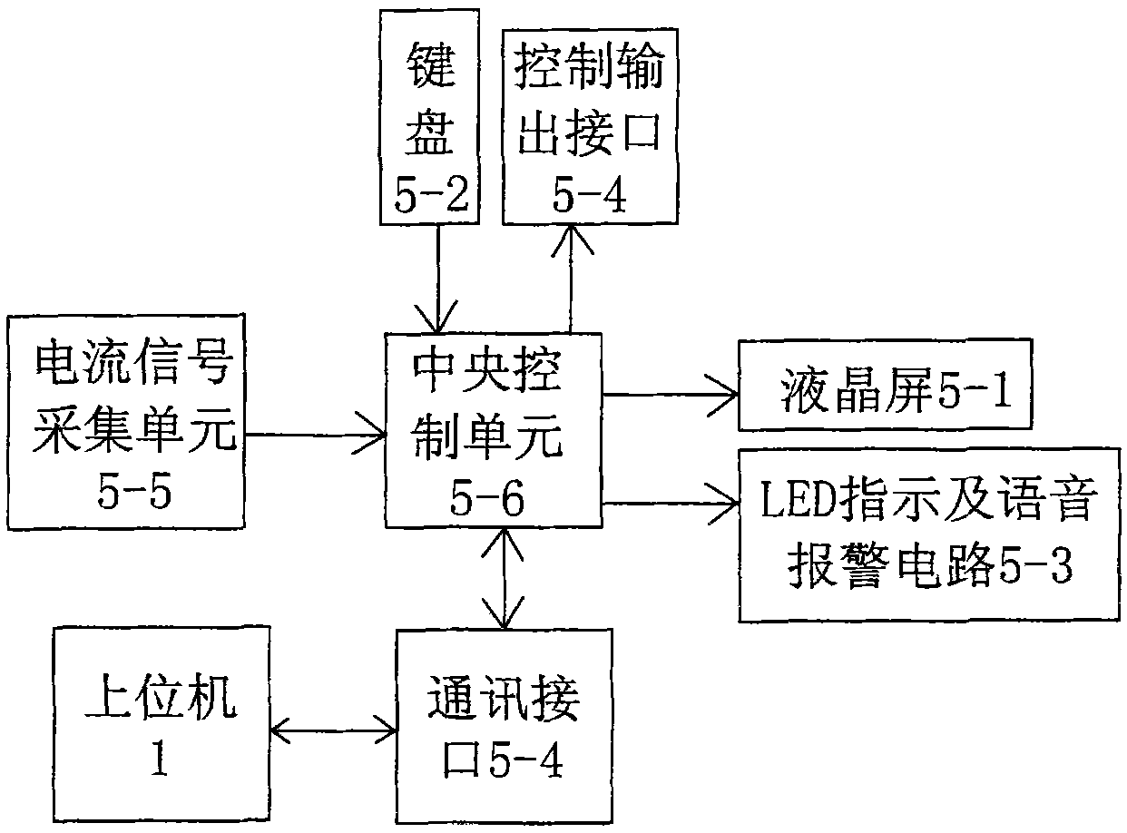
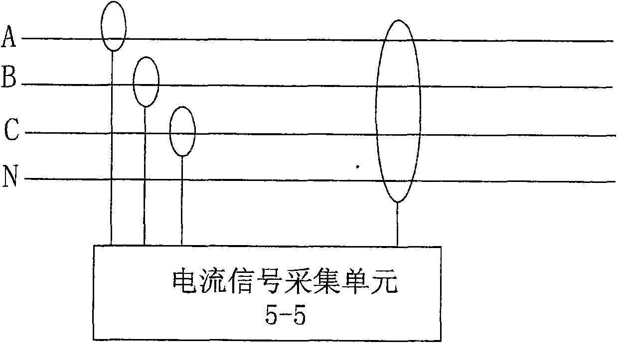
[0017] See Figure 1-8 , the electrical fire monitoring system of the present embodiment includes: an optical fiber temperature monitoring and alarming device 8, a residual current type electrical fire monitoring detector 5 and an alarm monitoring host 2; The monitoring information of the residual current electrical fire monitoring detector 5 is uploaded to the data concentrator 4 of the alarm monitoring host 2; the alarm monitoring host 2 communicates with the monitoring workstation 1 in real time through Ethernet, LAN or GPRS wireless network.

[0018] The data concentrator 4 is also connected to the wireless temperature monitoring and alarm device 7 for receiving the wireless monitoring information sent by the wireless temperature measurement module 9 via Ethernet or local area network.

[0019] Remote wireless communication is carried out between the wireless temperature measurement module 9 and the wireless temperature monitoring and alarm device 7 through a wireless data...


PUM


Abstract

The invention relates to an electrical fire monitoring system which comprises an optical fiber temperature monitoring alarm device, a residual current type electrical fire monitoring detector and an alarm monitoring host. The system also comprises a data concentrator, and the data concentrator is used for respectively receiving monitoring information from the optical fiber temperature monitoring alarm device and the residual current type electrical fire monitoring detector and uploading the monitoring information to the alarm monitoring host, through the Ethernet or a local network. The alarm monitoring host communicates with a monitoring workstation in real time through the Ethernet or local network or a GPRS (General Packet Radio Service) wireless network. The optical fiber temperature monitoring alarm device and the residual current type electrical fire monitoring detector are respectively used for monitoring the temperature information of power equipment and the residual current information of each return circuit and transmitting the monitoring information to the data concentrator. The data concentrator uploads the monitoring information to the monitoring host through the Ethernet or local network after processing the monitoring information, and the monitoring host displays whether the power equipment is overheated and the residual current in the return circuit exceeds limits or not in real time and gives an early warning or alarm when an exception occurs.

Description

technical field [0001] The invention relates to an electric fire monitoring system. Background technique [0002] The main causes of electrical fires are as follows: 1. Leakage; 2. Short circuit; 3. Overload. Electrical fires caused by heating of electrical equipment accounted for more than 60% of all electrical fires; in addition, leakage current faults (and caused by leakage current sparks) caused by insulation damage and humid environment The cause of fire accounts for more than 10% of the total. [0003] When the leakage current generated on the damaged line reaches 300-500mA, the damaged part will generate spark discharge with the adjacent grounding conductor. At this time, the released electric spark can easily ignite the surrounding combustibles and combustibles, thus causing a fire accident. Even if there is no flammable or combustible material around, the spark discharge generated by the leakage current can also accelerate the damaged area of ​​the insulation, ca...

Claims


Application Information

Patent Timeline
Patent Type & Authority Applications(China)
IPC IPC(8): G08B17/06G01R19/00G01K11/32G08B25/00
Inventor 顾海勇
Owner 陕西银河电力仪表股份有限公司
Why Eureka
Try Eureka