Structure for connecting heat insulation oil pipes

A technology for connecting structure and insulating oil pipes, which is applied in the direction of protecting pipes, pipes/pipe joints/fittings, and drilling pipes through heat insulation, which can solve the problems of leakage and inability to solve the connection structure of heat-insulating oil pipes, so as to reduce conduction and improve Insulation condition, effect of lowering temperature

Active Publication Date: 2011-03-30
JIANGSU CHANGBAO STEELTUBE CO LTD
View PDF7 Cites 15 Cited by
  • Summary
  • Abstract
  • Description
  • Claims
  • Application Information

AI Technical Summary

Problems solved by technology

Therefore, this structural scheme cannot solve the leakage problem encountered in the existing heat insulation oil pipe connection structure

Method used


Image

  • Structure for connecting heat insulation oil pipes
  • Structure for connecting heat insulation oil pipes
  • Structure for connecting heat insulation oil pipes

Examples


Embodiment 1

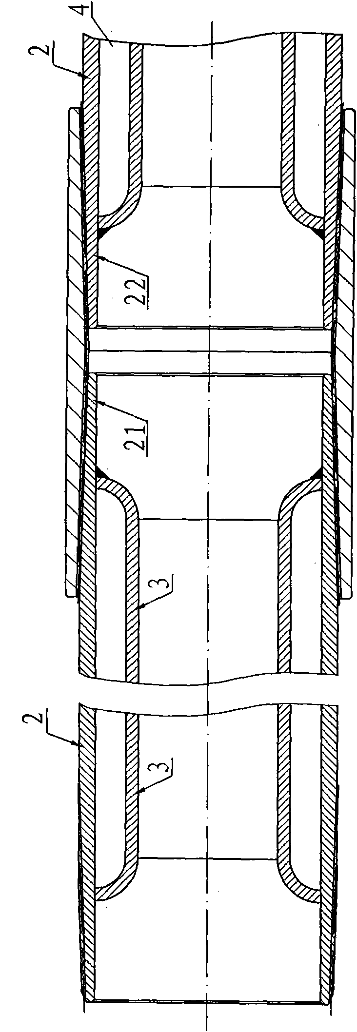
[0035] Embodiment 1: A connection structure of heat-insulated oil pipes, such as image 3As shown, it includes the coupling 1, the factory end 21 of the outer pipe threaded with the left end of the coupling 1, the user end 22 of the outer pipe threaded with the right end of the coupling 1, and the factory end 21 of the outer pipe is welded sealingly with the inner pipe factory end 31, in the user end outer tube 22, the inner tube user end 32 is welded sealingly, and the inner tube of the tube end is arranged between the inner tube factory end 31 and the inner tube user end 32 of the tube body, and the inner tube of the tube end is formed by the left The inner pipe 51 of the pipe end and the inner pipe 52 of the right pipe end are composed, the left end of the inner pipe 51 of the left pipe end is sealed and fixed together with the factory end 31 of the pipe body, and the right end of the inner pipe 52 of the right pipe end is sealed with the user end 32 of the pipe body Fixed ...

Embodiment 2

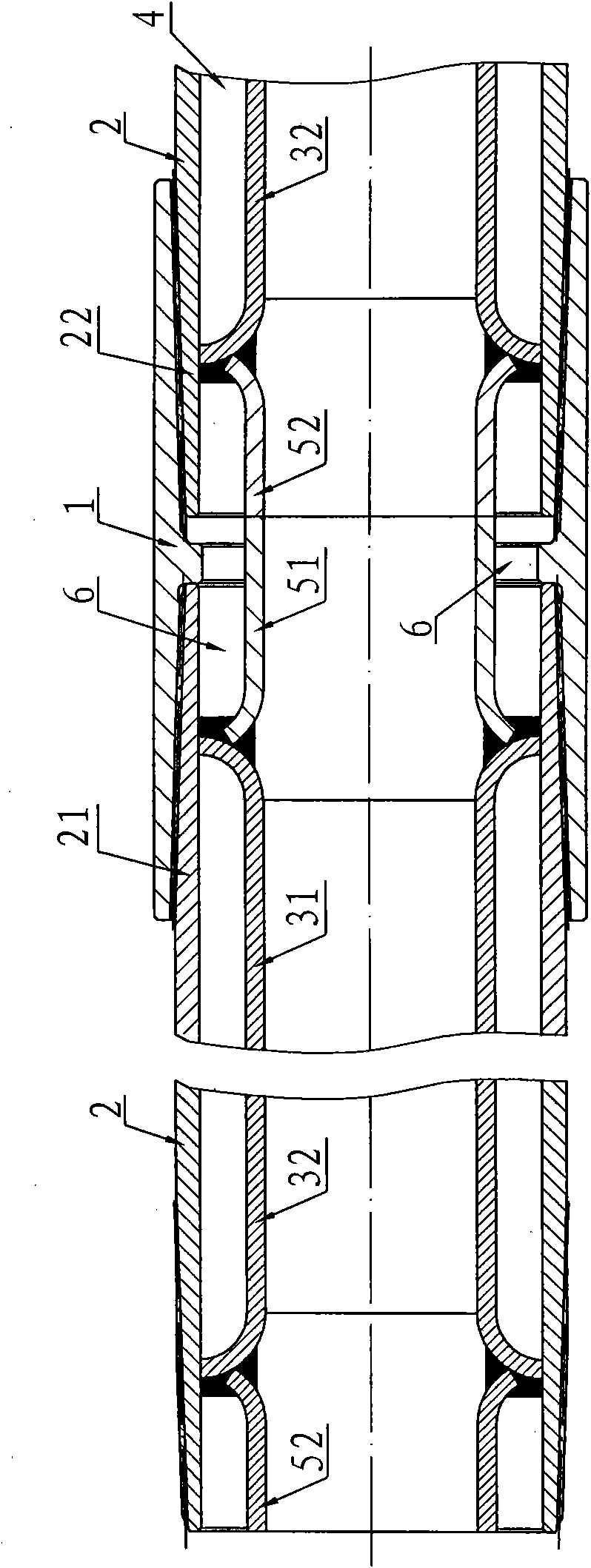
[0037] Embodiment 2: On the basis of Embodiment 1, a heat insulation sleeve 7 made of ceramic fibers is added in the closed pipe end heat insulation cavity 6, such as Figure 4 As shown, the outer circle and the inner hole wall of the heat insulation sleeve 7 are covered with aluminum foil 8, such as Figure 9 As shown, in this way, the heat insulation performance at the joint of the coupling 1 can be better, and the heat loss here can be further reduced.

Embodiment 3

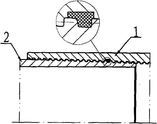
[0038] Embodiment 3: On the basis of Embodiment 1, the sealing structure between the inner pipe 51 at the left pipe end and the inner pipe 52 at the right pipe end can be selected as follows Image 6 The shown axial end face interference butt seal structure; or select Figure 7 The combination of axial end surface interference butt seal and cylindrical surface radial interference fit seal; or select Figure 8 The combined structure of axial end surface interference butt joint seal and conical surface radial interference fit seal shown; the threaded end surface connecting the outer pipe factory end 21 and coupling 1 and the connecting thread end surface of the outer pipe user end 22 and coupling 1 are provided with The torque shoulder 9, and the included angle α between the end surface 91 of the outer pipe in the torque shoulder 9 and the limiting end surface 92 of the inner thread of the coupling and the positive direction of the thread axis is 90°. The role of setting the to...


PUM


Abstract

The invention discloses a structure for connecting heat insulation oil pipes, which comprises a coupling, an outer pipe factory end, an outer pipe user end, a pipe body inner pipe factory end, a pipe body inner pipe user end and a pipe end inner pipe, wherein the pipe end inner pipe is arranged between the pipe body inner pipe factory end and the pipe body inner pipe user end, and consists of a left pipe end inner pipe and a right pipe end inner pipe; one end of the left pipe end inner pipe is welded to the pipe body inner pipe factory end; one end of the right pipe end inner pipe is welded to the pipe body inner pipe user end; a sealed pipe end heat insulation cavity is formed between the pipe end inner pipe and the pipe body inner pipe factory end, the outer pipe factory end, the coupling, the pipe body inner pipe user end and the outer pipe user end; and a heat insulation sleeve is arranged in the pipe end heat insulation cavity. The pipe end inner pipe can reduce heat conduction, convection, radiation and heat loss at the coupling, improve the sealing performance of the heat insulation oil pipe coupling and prevent the problem that the heat insulation oil pipe coupling is easy to corrode at high temperature.

Description

technical field [0001] The invention relates to a connection structure of heat-insulating oil pipes for thermal recovery of heavy oil, in particular to a connection structure of heat-insulation oil pipes. Background technique [0002] Crude oil with high viscosity and high specific gravity is called heavy oil. The viscosity of heavy oil changes significantly with temperature. Tests show that for heavy oil, if the temperature increases by 8-9 °C, its viscosity can be reduced by half. Therefore, for the exploitation and transportation of heavy oil, heat is often used to reduce its viscosity; injecting steam into the underground heavy oil layer is the main technical measure for the exploitation of heavy oil in the petroleum industry at present, which is called "steam huff and puff method for thermal recovery of heavy oil" or "Steam drive method". [0003] When injecting steam (200℃~350℃) into the ground, in order to reduce the loss of heat and reduce the cost of thermal recov...

Claims


Application Information

Patent Timeline
Patent Type & Authority Applications(China)
IPC IPC(8): E21B17/02E21B43/24F16L59/18
Inventor 周家华
Owner JIANGSU CHANGBAO STEELTUBE CO LTD
Why Eureka
Try Eureka