
Partition plate device of casting system of double-roller continuous casting machine
A technology of casting system and continuous casting machine, which is applied in the field of twin-roller continuous casting machine to manufacture composite steel plates, can solve the problems of secondary oxidation of molten steel and narrow casting space, etc. Reduce the effect of shock
- Summary
- Abstract
- Description
- Claims
- Application Information
AI Technical Summary
Problems solved by technology
Method used
Image

Examples
Embodiment Construction
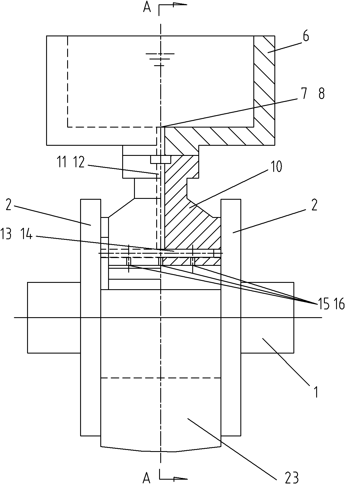
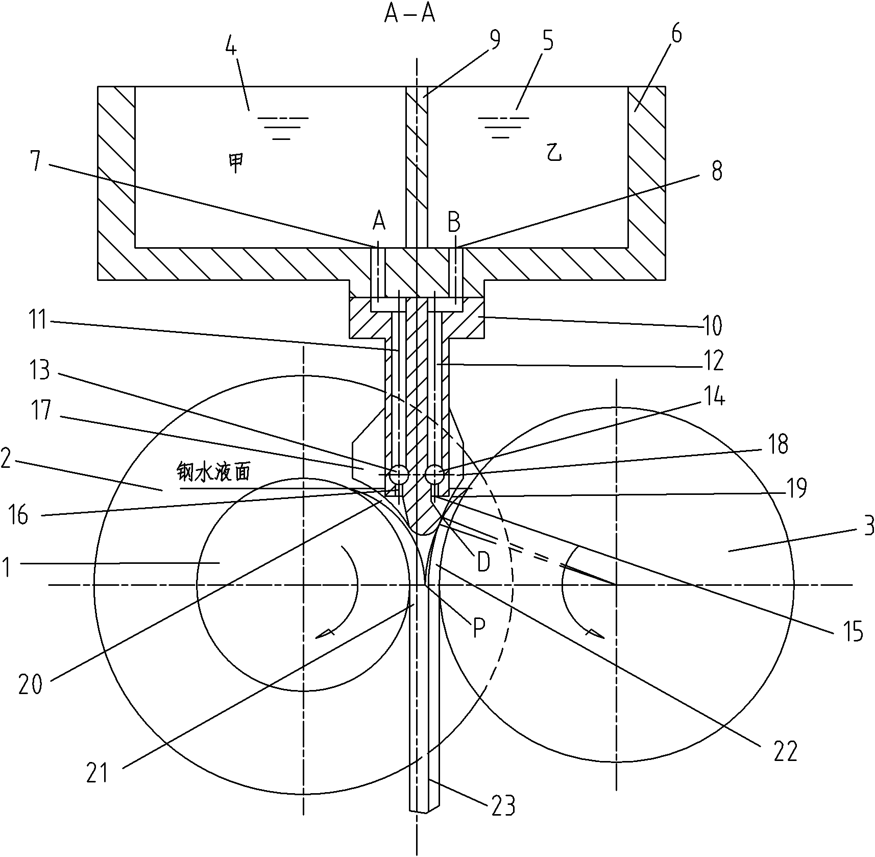
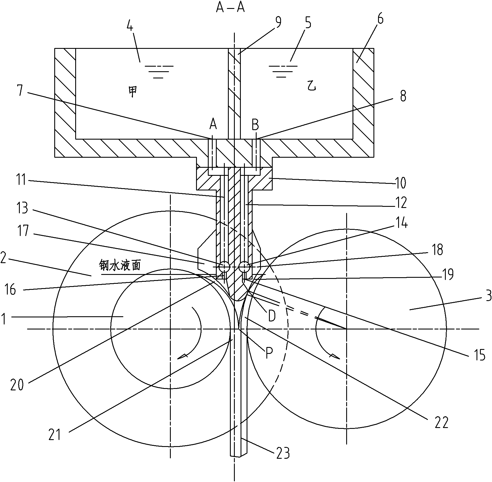
[0016] The present invention will be further described below with reference to the accompanying drawings. like Figure 1-2 As shown, a partition device for a casting system of a twin-roll continuous casting machine includes a partition 10, a tundish tank 6, a tundish tank casting channel A7, a tundish tank casting channel B8, a tundish tank partition wall 9, a partition plate casting channel A11, The baffle casting channel B12, the collector hole A13, the collector hole B14, the flow distribution hole A16, the flow distribution hole B15, the side wing plate A17 and the side wing plate B18, the baffle plate 10 is installed in the lower part of the intermediate tank 6, the The intermediate tank partition wall 9 is installed in the middle of the intermediate tank 6, the intermediate tank 6 is divided into two molten steel chambers, and the intermediate tank casting channel A7 and The intermediate tank casting channel B8 is provided with a partition casting channel A11 and a part...
PUM
 Abstract
Description
Claims
Application Information