Electric power assisted bicycle

An electric power assist and bicycle technology, applied in the direction of bicycles, electric vehicles, motor vehicles, etc., can solve problems such as prolonging the output time, and achieve the effect of feeling good

Inactive Publication Date: 2011-04-27
SUNSTAR GIKEN KK
View PDF1 Cites 10 Cited by
  • Summary
  • Abstract
  • Description
  • Claims
  • Application Information

AI Technical Summary

Problems solved by technology

That is, since the output time is prolonged in proportion to the duration of the pedaling force detected by the pedal de

Method used


Image

  • Electric power assisted bicycle
  • Electric power assisted bicycle
  • Electric power assisted bicycle

Examples


Embodiment Construction

[0071] Embodiments of the present invention will be described below with reference to the drawings.

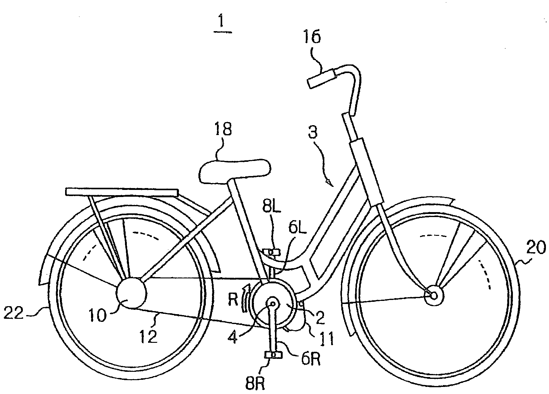
[0072] figure 1 A schematic structure of the electric assist bicycle 1 is shown. As shown in the figure, like a normal bicycle, the main frame portion of the electric power-assisted bicycle 1 is composed of a metal tube frame 3, and a front wheel 20 and a rear wheel 22 are mounted on the frame 3 in a known manner. , handlebar 16 and saddle 18.

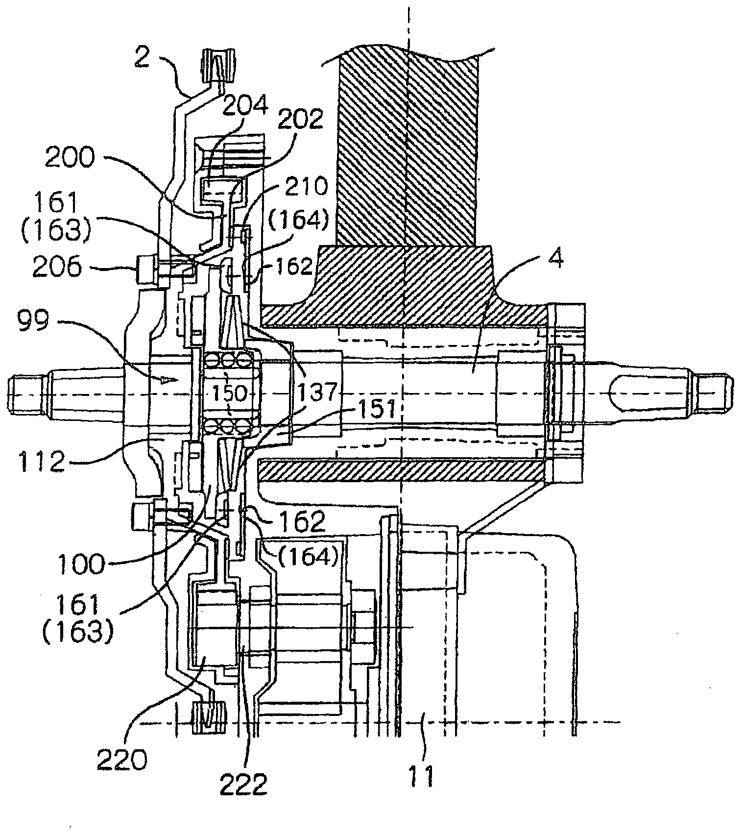
[0073] Further, a propeller shaft 4 is rotatably supported at the center lower portion of the vehicle frame 3, and pedals 8L, 8R are attached to the left and right end portions via pedal cranks 6L, 6R, respectively. On this propeller shaft 4, a one-way clutch (described later) is used to transmit only rotation in the R direction corresponding to the forward direction of the vehicle body. image 3 99) sprocket wheel 2 is installed coaxially. A chain 12 rotating endlessly is stretched between the sprocket 2 and the rear wheel power ...


PUM


Abstract

An electric power assisted bicycle capable of smooth electric power assisted travel giving a good feeling by supplying an assisting power with a high follow-up performance by making the following control even when climbing a slope. The pedaling force FL, the vehicle speed V, the crank angle Theta, the start angle Thetas, the maximum pedaling angle Thetam0, and the end angle Thetae0 are determined (step 350). The assisting power is calculated from the pedaling force FL and the vehicle speed V (step 352) so as to make motor control (step 354). During the assisting operation, it is judged whether or not the bicycle is climbing a slope on the basis of the pedaling force FL and the crank angle Theta (step 356). If it is judged that the bicycle is climbing a slope and when the crank angle reaches a start angle at which the assisting power for slope climb is applied (at step 358, an affirmative decision), the assisting power for slope climb is re-calculated from the pedaling force FL, the vehicle speed V, and the crank angle Theta, and the motor is controlled (step 360).

Description

technical field [0001] The present invention relates to an electric assist bicycle that can be ridden comfortably and comfortably even on an uphill slope. Background technique [0002] Conventionally, in electric assist bicycles, the assist output from the electric motor is determined by the product of the detected pedaling force and the assist ratio (the ratio of the assist output of the electric motor to the pedaling force) determined from the vehicle speed and the like. [0003] Actually, when the pedals are stepped on, the pedaling force increases from the pedaling start angle, becomes maximum at the maximum pedaling force angle, and becomes substantially zero at the end angle (refer to Figure 8 ). This cycle repeats alternately on the left and right pedals. Therefore, if Figure 17 As shown in 260 and 261 of , the variation of the pedal force contributed by the left and right pedals is sinusoidal. Here, if one of the peaks 260 and 261 of two adjacent pedaling cycles...

Claims


Application Information

Patent Timeline
IPC IPC(8): B62M23/02B62M6/50
CPCB60L15/20Y02T10/70B60L11/1801B60L11/007B62M6/50Y02T10/7005B60L2200/12B60L50/20B62M6/55Y02T10/64Y02T10/72
Inventor 吉家彰人山口胜浩
Owner SUNSTAR GIKEN KK
Why Eureka
Try Eureka