Apparatus for treating discharge gas and system for treating discharge gas

A waste gas treatment device and waste gas technology, which are applied in gas treatment, combustion product treatment, climate sustainability, etc., can solve the problems of limited contact area of ​​denitration catalyst, difficulty in further improving the efficiency of mercury oxidation reaction, etc., and increase the contact time. Effect

Inactive Publication Date: 2011-06-15
MITSUBISHI HEAVY IND LTD
View PDF2 Cites 6 Cited by
  • Summary
  • Abstract
  • Description
  • Claims
  • Application Information

AI Technical Summary

Problems solved by technology

[0023] However, conventionally, the gas flow of the exhaust gas 12 supplied to the denitration catalyst layer 13 is rectified by a rectifying mechanism (not shown) in front of the denitration catalyst layer 13 to become a laminar flow state, and flows into the denitration catalyst layer 13 in this state. Therefore, the contact area with the denitration catalyst is limited, and as a result, there is a problem that it is difficult to further improve the oxidation reaction efficiency of mercury.

Method used


Image

  • Apparatus for treating discharge gas and system for treating discharge gas
  • Apparatus for treating discharge gas and system for treating discharge gas
  • Apparatus for treating discharge gas and system for treating discharge gas

Examples


Embodiment 1

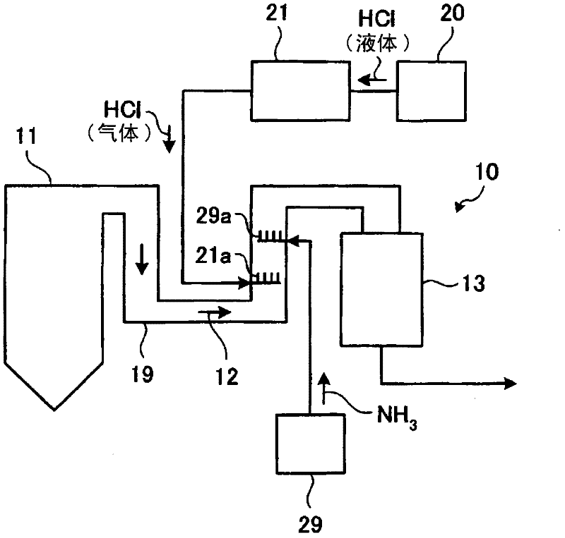
[0050] An exhaust gas treatment system to which an exhaust gas treatment device according to an embodiment of the present invention is applied will be described with reference to the drawings. In addition, since the structure of the exhaust gas treatment system to which the exhaust gas treatment device of this embodiment is applied Figure 12 The shown exhaust gas treatment systems have the same structure, so in this embodiment, only the structure of the exhaust gas treatment device will be described.

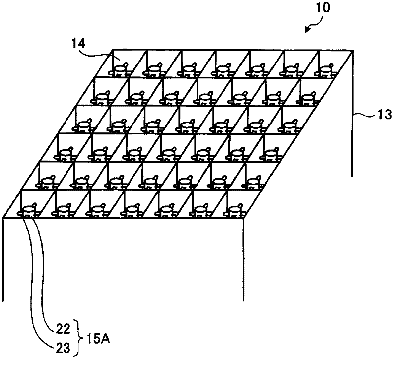
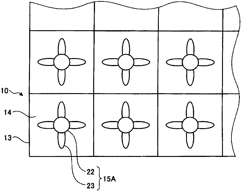
[0051] figure 1 is a schematic diagram showing an exhaust gas treatment device of an embodiment, figure 2 is a perspective view showing a part of the structure of the denitration catalyst layer, image 3 is a diagram when the swirling flow generating member is viewed from a direction perpendicular to the vertical axis direction, Figure 4 This is a diagram when the swirling flow generating member is viewed from the vertical axis direction of the denitration catalyst layer. ...

Embodiment 2

[0076] An exhaust gas treatment system to which an exhaust gas treatment device according to an embodiment of the present invention is applied will be described with reference to the drawings. In addition, in this embodiment, similarly to Embodiment 1, since the structure and Figure 12 The shown exhaust gas treatment systems have the same structure, so in this embodiment, only the structure of the exhaust gas treatment device will be described.

[0077] In addition, since the structure of the exhaust gas treatment device of this embodiment is the same as the exhaust gas treatment device of the above-mentioned first embodiment, the diagram showing the structure of the exhaust gas treatment device will be omitted, and only the figure showing the structure of the swirling flow generating member will be used for description. .

[0078] Figure 5 is a diagram when the swirling flow generating member is viewed from a direction perpendicular to the vertical axis direction, Image ...

Embodiment 3

[0084] An exhaust gas treatment system to which an exhaust gas treatment device according to an embodiment of the present invention is applied will be described with reference to the drawings. In addition, in this example, similarly to Example 1, the structure and Figure 12 The shown exhaust gas treatment systems have the same structure, so in this embodiment, only the structure of the exhaust gas treatment device will be described.

[0085] In addition, since the structure of the exhaust gas treatment device of this embodiment is the same as the exhaust gas treatment device of the above-mentioned embodiment 1, the diagram showing the structure of the exhaust gas treatment device is omitted, and only the figure showing the structure of the swirling flow generating part is used. illustrate.

[0086] Figure 7 is a diagram when the swirling flow generating member is viewed from a direction perpendicular to the vertical axis direction, Figure 8 This is a diagram when the swir...


PUM


Abstract

An apparatus for discharge gas treatment (10) having a denitration catalyst layer (13) which removes nitrogen oxides from a discharge gas and in which hydrochloric acid is sprayed in the discharge gas to oxidize mercury. The apparatus has a spiral-flow generation member (15A) in each of passages (14) of the denitration catalyst layer (13). The member (15A) comprises: a vertical shaft (22) disposed in the passage (14) of the honeycomb catalyst; and sets of four spiral-flow generation blades (23) which have been disposed radially on the vertical shaft (22) and cause a turbulent flow in the discharge gas, the sets of the spiral-flow generation blades (23) having been arranged at a given interval in the direction of the vertical shaft (22). By thus generating a spiral flow in the discharge gas in each passage (14) of the denitration catalyst layer (13), the time period of contact of the discharge gas with the denitration catalyst is prolonged to improve the efficiency of the oxidation reaction of the mercury contained in the discharge gas with the denitration catalyst.

Description

technical field [0001] The present invention relates to an exhaust gas treatment device and an exhaust gas treatment system for treating exhaust gas discharged from a combustion device. Background technique [0002] For example, since exhaust gas discharged from a coal-fired boiler, which is a combustion device such as a thermal power plant, contains highly toxic mercury, various systems for removing mercury in exhaust gas have been considered conventionally. [0003] Generally, a coal-fired boiler is provided with a wet desulfurization device for removing sulfur components in exhaust gas. In the flue gas treatment equipment formed by attaching a desulfurization device to the boiler as a waste gas treatment device, it is known that when the chlorine (Cl) component in the waste gas increases, the divalent metallic mercury (Hg) soluble in water The proportion is increased, so that mercury is easily captured by the desulfurization device. [0004] Therefore, in recent years, ...

Claims


Application Information

Patent Timeline
Patent Type & Authority Applications(China)
IPC IPC(8): B01D53/94B01D53/64B01J35/04F23J15/00
CPCB01D2255/20761F23J2215/10B01D2255/30B01D2255/1025B01D2255/1028B01D2255/20738B01D2255/20723B01D53/8631B01D2255/20769B01D2255/20753B01D2255/1026B01D2255/20776F23J2215/60B01D2257/404Y02C20/10B01D53/64F23J2219/10F23J15/003B01D2255/20715B01D2255/20746B01D2255/20707B01D2255/1023B01D2251/502F23J2219/20B01D2255/2073B01D2255/1021F23J15/006B01D2257/602F23M9/003
Inventor 佐藤敏浩坂田展康四条利久磨村上盛纪鹈饲展行野地胜己清泽正志
Owner MITSUBISHI HEAVY IND LTD
Why Eureka
Try Eureka