
Compensation mechanism

A technology of compensation mechanism and four-bar linkage structure, applied in the direction of metal processing, etc., can solve the problem that the flexible hinge mechanism cannot realize the micro-movement displacement and so on

Active Publication Date: 2011-06-29
COMAC +1
View PDF6 Cites 0 Cited by
  • Summary
  • Abstract
  • Description
  • Claims
  • Application Information

AI Technical Summary

Problems solved by technology

However, neither the rail mechanism nor the flexible hinge mechanism can achieve the above-mentioned requirements for micro-motion displacement.

Method used


Image

  • Compensation mechanism
  • Compensation mechanism
  • Compensation mechanism

Examples


Embodiment Construction

[0032] The relationship between the X direction, the Y direction and the Z direction described below is that the X direction and the Y direction are perpendicular to each other on the horizontal plane, and the Z direction is perpendicular to the X direction and the Y direction on the vertical plane. However, it can be understood that X, Y and The Z direction is indicative rather than specific.

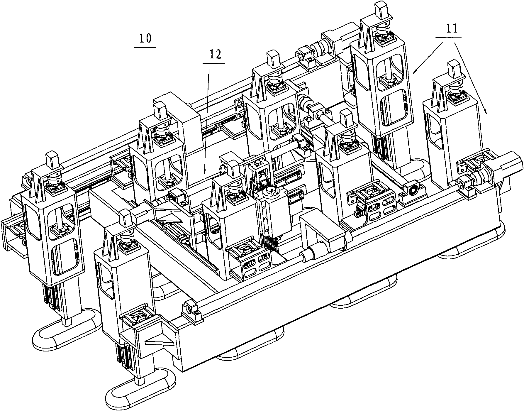
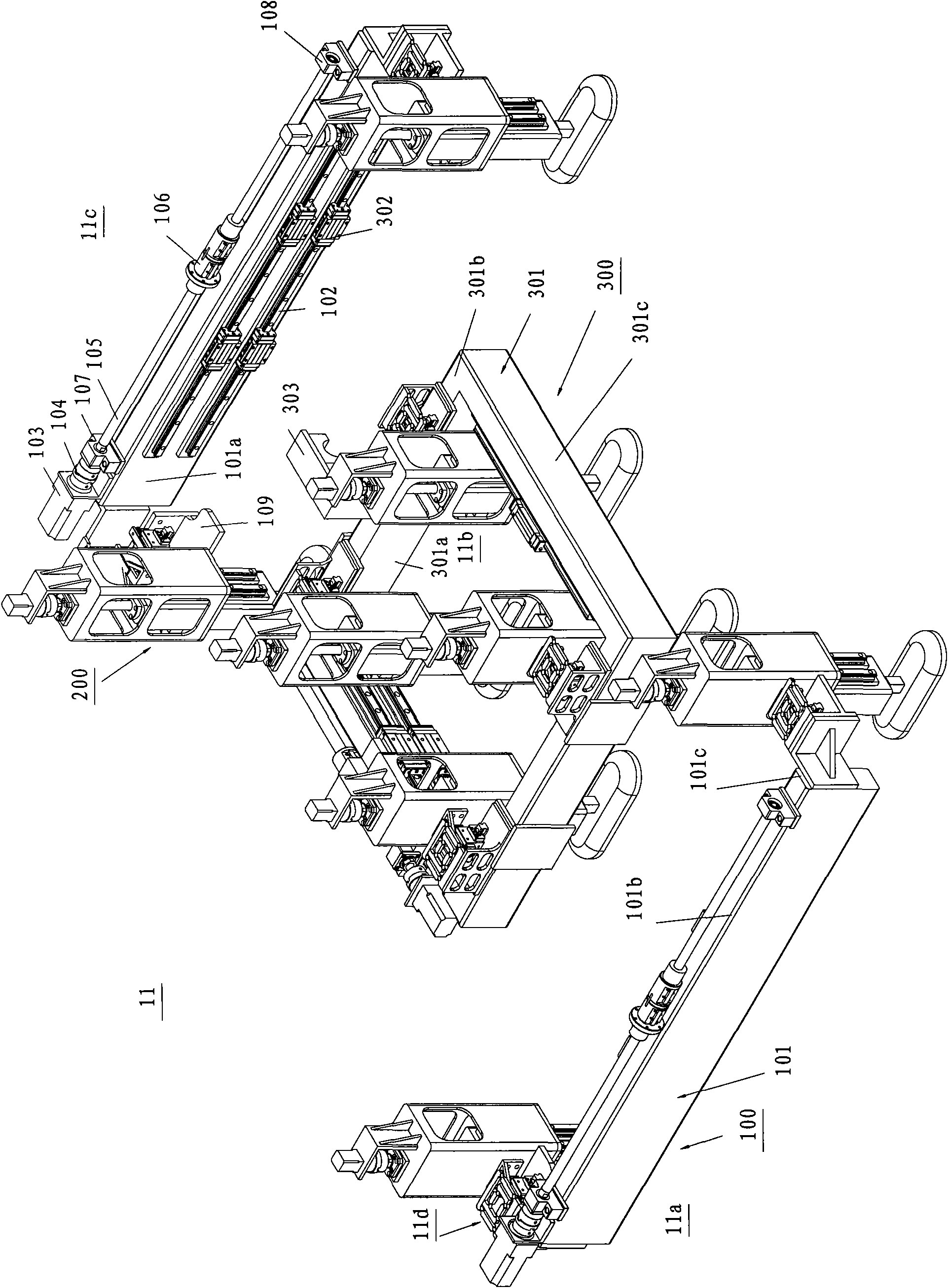
[0033] Such as figure 1 As shown, the walking positioning device (10) includes a traveling mechanism (11), a positioning mechanism (12), an actuator (not shown) and a central processing unit (not shown). The walking mechanism (11) can advance on the surface of the workpiece and reach the designated assembly area according to the instructions issued by the central processing unit, and the positioning mechanism (12) is used for precise positioning in the X and Y directions in the assembly area, that is, Find the X, Y coordinates and move the actuator to the specified coordinates accordi...


PUM


Abstract

The invention discloses a compensation mechanism, which comprises a first directional motion piece, a second directional motion piece, a first flexible hinge and a second flexible hinge, wherein the first flexible hinge and the second flexible hinge respectively form a four-connecting rod structure having two first directional connecting rods and two second directional connecting rods; the first directional motion piece is fixedly connected with one of the first directional connecting rods of the first flexible hinge; the second directional motion piece is fixedly connected with one of the second directional connecting rods of the second flexible hinge; and the other one of the first directional connecting rods of the first flexible hinge is fixedly connected with the other one of the second directional connecting rods of the second flexible hinge. The compensation mechanism is particularly used for a walking and positioning device and provides stable motion compensation on an XY plane through a simple structure, so that an actuator in the walking and positioning device can be aligned with the normal direction of a workpiece.

Description

technical field [0001] The invention relates to a compensating mechanism, in particular to a compensating mechanism used in a walking positioning device. Background technique [0002] In order to meet the high life requirements of modern aircraft and ensure the safety and reliability of mechanical connections, automatic hole making and even automatic drilling and riveting technology have become the development direction of assembly technology. As a new type of automatic assembly system, through a double-frame eight-leg walking positioning mechanism, coupled with the corresponding end effector, it can be adsorbed on the surface of aircraft products and automatically make holes for the mechanical connection parts. [0003] Movements in the X, Y, and Z directions can be realized in this mechanism. However, if the mechanism can ensure that the normal coincidence of the assembly position of the spindle and the surface of the workpiece at the target, then the A (rotation around th...

Claims


Application Information

Patent Timeline
IPC IPC(8): B23Q9/00
Inventor 王珉蒋红宇余路王宇波
Owner COMAC
Learn More