Method for using vanes to discharge flue gas and flue gas drain valve

A technology of flue gas discharge and blades, which is applied in the direction of lift valves, valve devices, engine components, etc., can solve the problems of reducing the area of ​​smoke exhaust, backflow of smoke gas, and poor sealing, so as to achieve smooth opening and closing, and eliminate smoke leakage Effect

Inactive Publication Date: 2012-09-12
张忠
View PDF0 Cites 0 Cited by
  • Summary
  • Abstract
  • Description
  • Claims
  • Application Information

AI Technical Summary

Problems solved by technology

The disadvantages of this smoke exhaust valve are: due to the existence of the fixed plate 2, the smoke exhaust area is objectively reduced, and due to the restriction of the installation position of the smoke exhaust pipe 5, the blades 4 cannot be fully opened, and the smoke exhaust The reduction of the area affects the smoke exhaust effect
However, due to structural constraints, there must be a gap between the rotating shaft on both sides of the blade and the blade, otherwise the blade cannot rotate
When the blades are closed, the seal is still not good
[0005] There are many defects in the structural design of the above-mentioned smoke exhaust valve. Since the blade must rotate around its shaft, the shaft must be fixed on the valve body, so there must be a gap between the blade, the shaft and the valve body, otherwise the blade cannot rotate.
The inevitable gap between the vane, the shaft and the valve body directly affects the seal between the outer contour edge of the vane and the valve body. When the vane is closed, the smoke will flow back due to poor sealing.
This problem has not been solved for many years

Method used


Image

  • Method for using vanes to discharge flue gas and flue gas drain valve
  • Method for using vanes to discharge flue gas and flue gas drain valve
  • Method for using vanes to discharge flue gas and flue gas drain valve

Examples


Embodiment Construction

[0032] The present invention will be described in detail below in conjunction with the accompanying drawings.

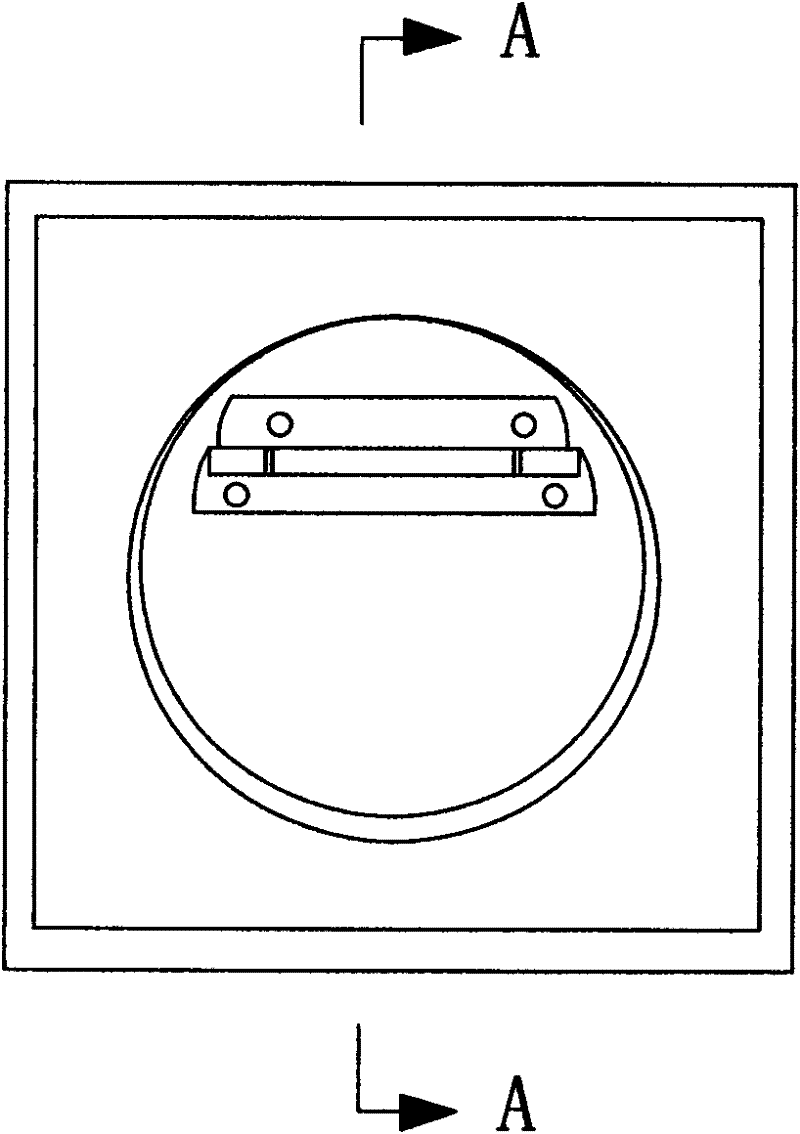
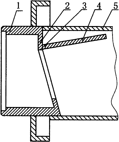
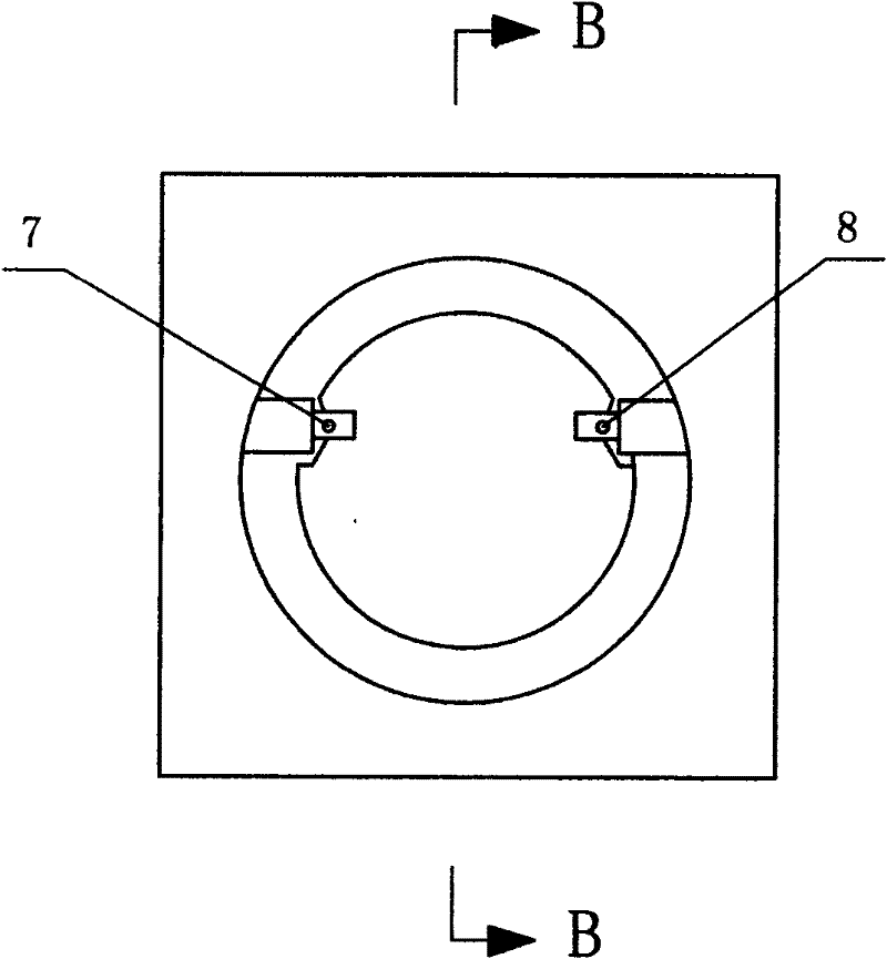
[0033] A method of using blades to discharge smoke according to the present invention includes a valve body and blades, a smoke exhaust port is set in the valve body, two blades are arranged in the smoke exhaust port, the blades can rotate around their rotating shafts, and the opening of each blade The opening and closing are both left and right. After the smoke exhaust starts, the two blades open around their rotating shafts, and the smoke exhaust port is unblocked; stage, the rotation directions of the two vanes are opposite, and a top-to-bottom sloping stop is set in the valve body. After the vanes are closed, they are all attached to the rear surface of the vane stop. on flat surface.

[0034] The specific structural examples of the smoke exhaust method of the present invention are set forth below.

[0035] Such as Figure 5 , 6 , 7, and 8, the present invent...


PUM


Abstract

The invention discloses a method using vanes to discharge flue gas and a flue gas drain valve, which belongs to the technical field of flue gas discharge. The flue gas drain valve comprises a valve body and vanes; a flue gas outlet is arranged in the valve body; the vanes are arranged in the flue gas outlet; and the vanes can rotate along rotating shafts thereof. The flue gas drain valve is characterized in that two vanes are adopted; each vane is opened left and right; when the flue gases are discharged, the two vanes are opened respectively along the rotating shafts thereof, and the flue gas outlet is smooth; and when the discharge of the flue gases is stopped, the two vanes return, are closed and contacted with each other. As the vanes are opened left and right, the defects of a small flue gas discharge area and larger force needed for opening the vanes brought by an upper-lower opening way are avoided. As a front vane and a rear vane are overlapped when being closed, the two vanescan be completely sealed after being closed, and the reversing problem of oil smokes is solved. The outer edge parts of the front vane and the rear vane can not leak smoke, which completely stops thephenomenon of smoke leaking. The invention can be used for flue terminals and ventilators, and can also be broadly used for opening and sealing gas and liquid flows.

Description

technical field [0001] The invention belongs to the technical field of smoke exhaust, and in particular relates to a smoke exhaust valve and a smoke exhaust method. Background technique [0002] Valves that control the discharge and sealing of gases and liquids are required in many fields. For all kinds of valves, the sealing problem is very important. For example, the good smoke exhaust effect of the building smoke exhaust system has always been a problem that technicians in related fields have been working hard to solve. The smoke exhaust valve located at the flue opening plays a key role in smoke exhaust. The smoke exhaust valve in the prior art is composed of a valve body and blades, and smoke exhaust and sealing are realized by opening and closing the blades. When the kitchen range hood is working, the airflow momentum generated by the oily fume breaks through the blades, and the oily fume enters the flue in the building. When the range hood is not working, the blade...

Claims


Application Information

Patent Timeline
Patent Type & Authority Patents(China)
IPC IPC(8): F16K1/20F16K1/36
Inventor 张忠
Owner 张忠
Why Eureka
Try Eureka