
Modeling method and device for PPL (polarize power loss) of multi-antenna channel

A channel polarization and power loss technology, applied in the field of communication, can solve problems such as multi-antenna channel polarization power loss modeling schemes that have not yet been provided

Active Publication Date: 2014-12-10
产学研共同体(山东)科技成果转化有限公司
View PDF3 Cites 0 Cited by
  • Summary
  • Abstract
  • Description
  • Claims
  • Application Information

AI Technical Summary

Problems solved by technology

[0005] The miniaturization and high density characteristics of the multi-antenna of the mobile terminal determine the effective representation of the multi-polarization power loss of the terminal. However, the inventors found that there is no modeling scheme for the multi-antenna channel polarization power loss.

Method used


Image

  • Modeling method and device for PPL (polarize power loss) of multi-antenna channel
  • Modeling method and device for PPL (polarize power loss) of multi-antenna channel
  • Modeling method and device for PPL (polarize power loss) of multi-antenna channel

Examples


Embodiment Construction

[0023] It should be noted that, in the case of no conflict, the embodiments in the present application and the features in the embodiments can be combined with each other. The present invention will be described in detail below with reference to the accompanying drawings and examples.

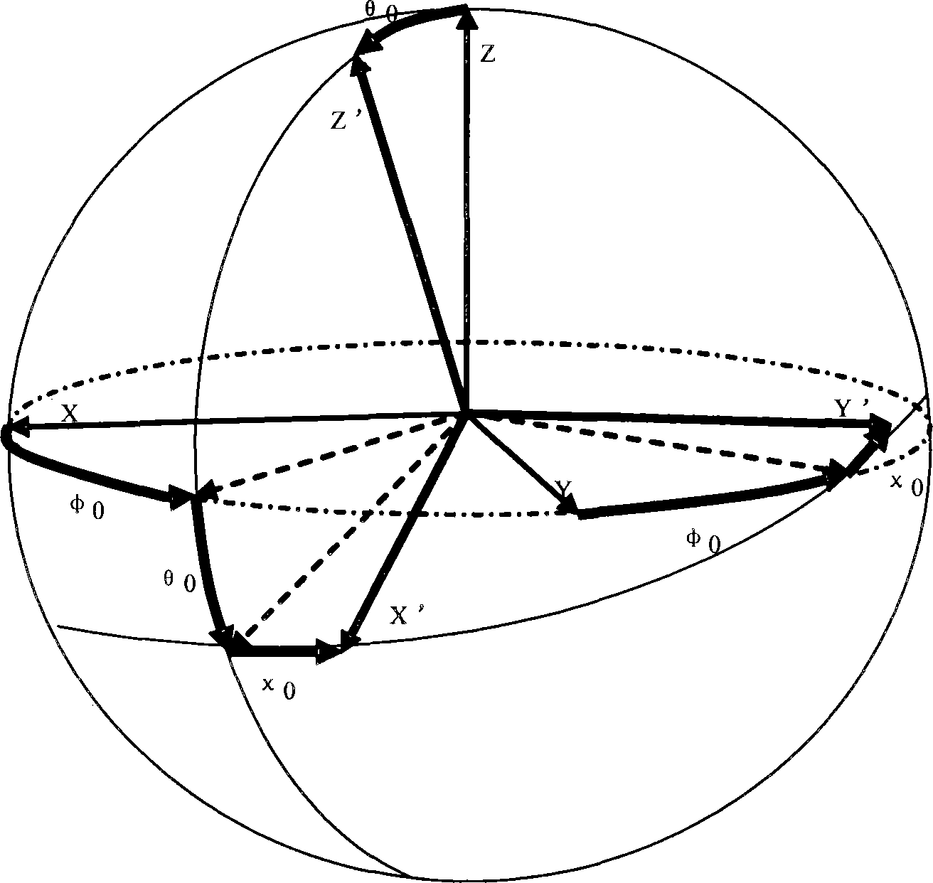
[0024] According to an embodiment of the present invention, a modeling method for multi-antenna channel polarization power loss is provided, and the terminal multi-antenna channel is considered as a three-port microwave network, such as image 3 As shown, two road ports and one field port, using the S-parameter characterization method of the three-port network and the polarization characteristic characterization method of the antenna radiation electric field, establish the field-circuit transformation matrix model, extract the integrated polarization extension information of the field and circuit, and obtain A general representation model for cross-polarization spreading properties of antenna c...


PUM


Abstract

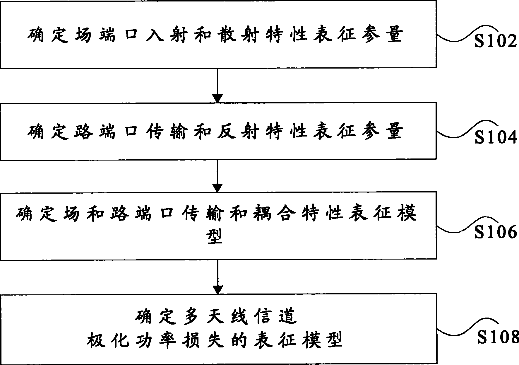
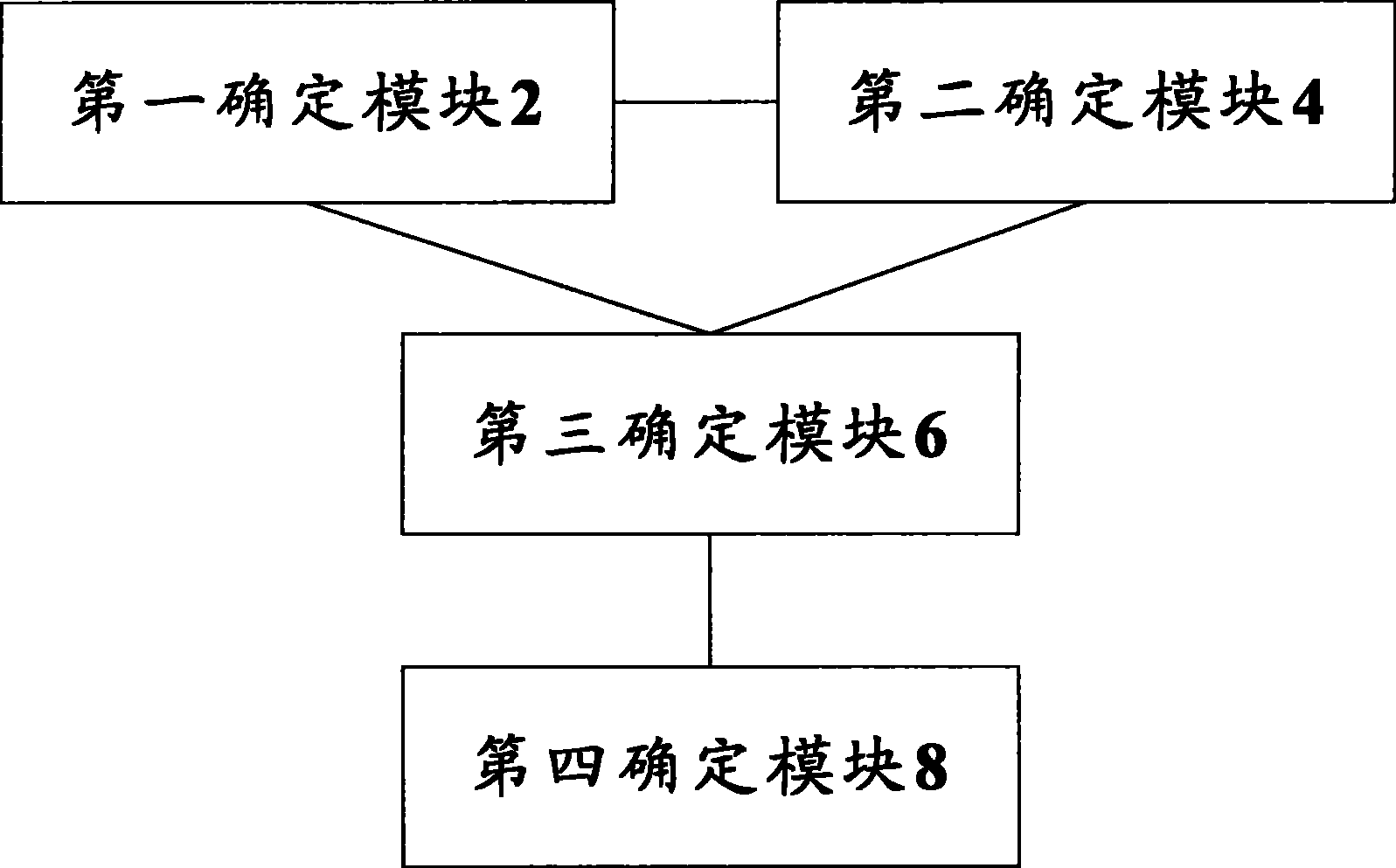
The invention discloses a modeling method and device for the PPL (polarize power loss) of a multi-antenna channel. The method disclosed by the invention comprises the following steps: determining the characterization parameters of incident and scattering properties of a field port; determining the characterization parameters of transmission and reflection properties of a routed port; determining a characterization model of transmission and coupling properties of the field port and the routed port; and determining a characterization model of the PPL (polarize power loss) of the multi-antenna channel. The method and device disclosed by the invention provide a guarantee for the performance research, testing and certification of multiple antennas at a mobile terminal.

Description

technical field [0001] The present invention relates to the communication field, in particular to a multi-antenna channel polarization power loss (Polarize Power Loss, PPL for short) modeling method and device. Background technique [0002] Currently, the channel models SCM (Special Channel Model) and SCME (Special Channel Model Enhanced) adopted by the Third Generation Partnership Project (3GPP) and the WINNER (Wireless World Initiative New Radio) project team are quasi-physical models. Because the physical spatial position of the scatterers in this model is uncertain, the channel modeling method is only based on the outgoing wave direction and the incoming wave direction (Direction of Arrival (referred to as DOA)) information of the scatterers near the two ends of the channel. Conceptually In other words, 3GPP's SCM can support antenna arrays with arbitrary topological structures. However, SCM, SCME and WIM only consider Uniform Linear Array (ULA for short) in their more d...

Claims


Application Information

Patent Timeline
Patent Type & Authority Patents(China)
IPC IPC(8): H04B7/02H04L1/06
CPCY02D30/70
Inventor 黄旭彭宏利禹忠
Owner 产学研共同体(山东)科技成果转化有限公司
Learn More