Reel and transformer utilizing same

A transformer and winding frame technology, applied in the direction of transformer/inductor coil/winding/connection, etc., can solve problems such as pin displacement, welding inconvenience, winding frame melting loss, etc., so as to solve the problem of pin displacement and reduce theoretical Line man-hours, improve the effect of tin overflow or tin hole

Inactive Publication Date: 2011-11-09
DELTA ELECTRONICS INC
View PDF3 Cites 5 Cited by
  • Summary
  • Abstract
  • Description
  • Claims
  • Application Information

AI Technical Summary

Problems solved by technology

[0004] The object of the present invention is to provide a winding frame, which improves the pins of the existing winding frame, and is used to clamp the outlet part of the winding wire on the clamping part of the pins, so as to solve the problem that the existing pins are too thick , Inconvenient welding, too large tin cone and easy short circuit defects, and avoid pin deformation and reduce the man-hours of cable management, thereby effectively improving the phenomenon of tin overflow or tin holes. In addition, it also solves the problems caused by the melting loss of existing winding frames The problem of pin displacement

Method used


Image

  • Reel and transformer utilizing same
  • Reel and transformer utilizing same
  • Reel and transformer utilizing same

Examples


Embodiment Construction

[0036] Some typical embodiments embodying the features and advantages of the present invention will be described in detail in the description in the following paragraphs. It should be understood that the present invention can have various changes in different embodiments, but none of them departs from the scope of the present invention, and the description and drawings therein are used as illustrations in nature, not to limit the present invention. invention.

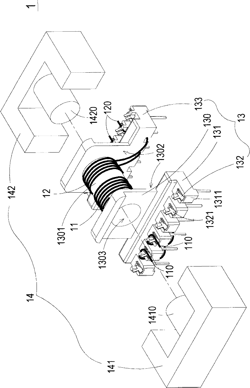
[0037] see figure 1 , which is a schematic diagram of a transformer structure in a preferred embodiment of the present invention. like figure 1 As shown, the transformer 1 of the present invention at least includes a primary winding 11, a secondary winding 12, a winding frame 13 and a magnetic core set 14, wherein the winding frame 13 includes a body 130, a first socket 131 and a plurality of clips Pin 132 is fixed. In this embodiment, the primary winding 11 and the secondary winding 12 can be a single core wire or ...


PUM


Abstract

The invention discloses a transformer and a reel. The transformer comprises at least one primary winding, at least one secondary winding, the reel and a magnetic core group, wherein the reel comprises a reel body, a first pin seat and a plurality of clamping pins; the reel body is provided with at least one winding area where the primary windings and the secondary windings are wound; the first pin seat is arranged at the bottom of the reel body; the plurality of clamping pins are arranged on the first pin seat; each clamping pin is provided with a clamping part; the clamping parts are used for clamping outgoing parts of the primary windings or the secondary windings onto the first pin seat; and at least a part of the magnetic core group is arranged in the reel. The transformer has the following beneficial effects: the pins are not easy to deform; the wires are easy to arrange; the wire arrangement time is reduced; and the problem of poor tinning during the welding of the pins can be avoided.

Description

technical field [0001] The invention relates to a winding frame and a transformer, in particular to a winding frame with clamping pins and a transformer utilizing the winding frame. Background technique [0002] Transformers are electronic components often used in various electrical equipment to adjust different voltages so that the voltage reaches the applicable range of electrical equipment, thereby enabling electrical equipment to operate. Usually, the structure of a transformer mainly includes a winding frame, a magnetic core group, a primary winding, and a secondary winding, wherein the coils of the primary winding and the secondary winding are respectively twisted by a plurality of single core wires (or multi-strand wires) ), and the coils of the primary winding and the secondary winding are wound in the winding area of ​​the bobbin, so the transformer can pass the input voltage of the primary winding, and after the electromagnetic action of the magnetic core group, th...

Claims


Application Information

Patent Timeline
Patent Type & Authority Applications(China)
IPC IPC(8): H01F27/30H01F27/28
Inventor 廖高材
Owner DELTA ELECTRONICS INC
Why Eureka
Try Eureka