
Anti-sticky bottom soybean milk machine and its cooking method
A soymilk machine and a technology for cooking pulp, which are applied to milk substitutes, beverage preparation devices, household appliances, etc., can solve the problems of sticking bottom and affecting the taste of soymilk, and achieve the effect of improving taste and preventing sticking bottom.
- Summary
- Abstract
- Description
- Claims
- Application Information
AI Technical Summary
Problems solved by technology
Method used
Image

Examples
Embodiment 1
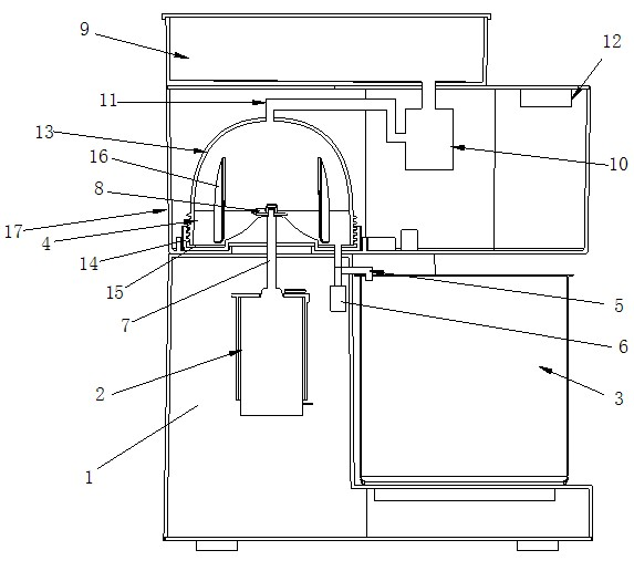
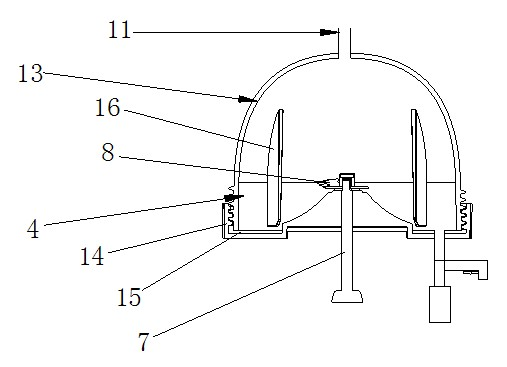
[0029] Such as figure 1 and figure 2 As shown, the present invention discloses an anti-sticky soybean milk machine, comprising a base 1 and a motor 2 arranged on the base 1, a cooking cup 3, and a crushing container 4, and the cooking cup 3 and the crushing container 4 are connected There is a slurry discharge pipeline 5, and the slurry discharge pipeline 5 is provided with a first control switch 6 for controlling its on-off, the motor 2 is connected with a crushing tool 8 through a blade shaft 7, and the blade shaft 7 extends into the crushing container 4, and The crushing tool 8 is located in the crushing container 4, and also includes a water tank 9, a second control switch 10, a water supply pipeline 11 and a control device 12, the water tank 9 is connected with the crushing container 4 through a water supply pipeline 11, and the second control switch 10 is located at the water supply pipeline 11 Above, it is used to control the on-off of the water supply pipeline 11 , a...
Embodiment 2
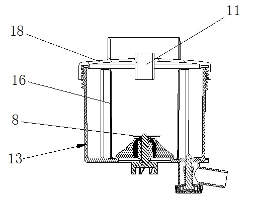
[0048] The structure of this embodiment is similar to that of Embodiment 1, the difference is that, as image 3 As shown, the crushing container 4 includes a container body 13 and a top cover 18 that is detachably and sealingly connected to the top of the container body 13. The middle part of the top cover 18 is provided with a second through hole, and the water adding pipeline 11 passes through the second through hole to connect with the crushing container 4. In communication, the top cover 18 and the container body 13 are connected through a threaded connection structure, and the top cover 18 and the container body 13 are also provided with a sealing ring 19 .
PUM
 Abstract
Description
Claims
Application Information