Dragging device for movable component on machine tool guide rail

A technology of moving parts and dragging devices, which is applied in the direction of auxiliary devices, metal processing machinery parts, toolholder accessories, etc., can solve the problems of increasing costs and increasing auxiliary processing time, etc., and achieves large dragging force and smooth dragging process Effect

Inactive Publication Date: 2013-01-23
南京星能传动机械有限责任公司
View PDF5 Cites 0 Cited by
  • Summary
  • Abstract
  • Description
  • Claims
  • Application Information

AI Technical Summary

Problems solved by technology

At present, lathe manufacturers often design separate driving devices for these accessories, which undoubtedly increases the cost; or simply use the machine tool to use the manufacturer's crane to assist the movement, which greatly increases the processing auxiliary time

Method used


Image

  • Dragging device for movable component on machine tool guide rail
  • Dragging device for movable component on machine tool guide rail

Examples


Embodiment 1

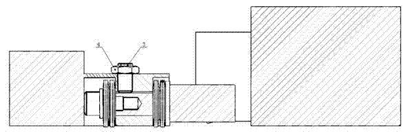
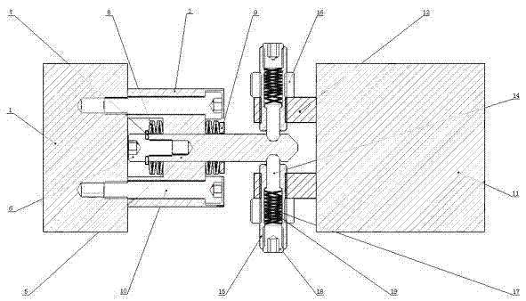
[0021] Embodiment 1: as figure 1 , figure 2 As shown, a dragging device for moving parts on a machine tool guide rail includes a bed saddle 1 and a pull rod 5 arranged on the bed, and a pull rod support 2 is fixedly connected to the bed saddle 1, and the pull rod 5 Threaded on the tie rod support 2, a tie rod buffer device is provided at one end of the tie rod 5 in contact with the tie rod support 2, and a tie rod fixing device is provided on the tie rod support 2 above the tie rod 5; There are two clamping devices on the moving part facing each other, and the ball studs of the two clamping devices are respectively inserted into the grooves at one end of the pull rod. The pull rod buffer device includes a first spring 8 , and the first spring 8 is fixed on the pull rod 5 through a first screw 6 , a first washer 7 , and a second washer 9 . The first spring 8 is a belleville spring. The clamping device includes a ball stud 14, the front end of the ball stud 14 is inserted in...

specific Embodiment approach

[0023] The saddle 1 of the horizontal lathe is provided with an independent driving source, which can move longitudinally along the guide rail of the bed, and can be precisely positioned at any position on the bed. When the tailstock 11 needs to be moved, the saddle 1 drives the pull rod 5 fixed on the support 2 to move towards the tailstock 11. Since the tailstock 11 is fixed on the bed through the pressure plate, the pre-tightening force of the spring 17 and the spring 19 is not enough. The tailstock is moved, and now the two ball studs are inserted into the grooves of the pull rod 5 (the pretightening force of the ball stud 14 can be adjusted by the set screw 18). Then loosen the pressure plate screw of the tailstock 11, the pre-tightening force of the spring 17 and spring 19 is greater than the frictional force of the tailstock, the bed saddle 1 drags the tailstock 11 to move to the position required for processing under the action of the driving source, and finally tighten...


PUM


Abstract

The invention mainly relates to an auxiliary moving device for parts movable along a guide rail on a machine tool. A dragging device for a movable component on a machine tool guide rail comprises a sliding base and a pull rod which are arranged on the bed of the machine tool, wherein a pull rod support is fixedly connected to the sliding base; the pull rod penetrates through the pull rod support;a pull rod buffering device is arranged on one end of the pull rod which contacts with the pull rod support; and a pull rod fixing device is arranged on the pull rod support above the pull rod. The dragging device further comprises at least two clamping devices arranged on the movable component, wherein the clamping devices are clamped in at least two grooves formed on the other end of the pull rod. With the dragging device, the whole dragging process is more stable; the pre-tightening force of a ball pin can be adjusted by turning a first fastening screw, thus obtaining greater dragger force; and when an operator forgets to loosen the pressing plate of a tail base, the ball pin can be automatically drawn out of the grooves of the pull rod without damaging the parts; therefore, the safetyprotection function is realized.

Description

technical field [0001] The present invention mainly relates to auxiliary moving devices for parts movable along guide rails on machine tools. Background technique [0002] When lathes process some shaft parts, in order to improve the machining accuracy, accessories such as center frame and idler device are often used, and the tailstock is also an indispensable part for processing shaft parts. These accessories will be moved to the appropriate position on the bed before processing, but do not need to be moved during processing. At present, lathe manufacturers often design separate driving devices for these accessories, which undoubtedly increases the cost; or simply use the manufacturer's crane to assist the movement with the help of the machine tool, which greatly increases the auxiliary processing time. Contents of the invention [0003] The object of the present invention is to avoid the deficiencies of the prior art and provide a dragging device that is easy to drag an...

Claims


Application Information

Patent Timeline
Patent Type & Authority Patents(China)
IPC IPC(8): B23Q1/72B23B25/00
Inventor 梁文勇杨福年
Owner 南京星能传动机械有限责任公司
Why Eureka
Try Eureka