Plasma slab lens and near-field focusing method thereof

A technology of flat lens and plasma, which is applied in the direction of lens, optics, instruments, etc., can solve the problems that the center cannot be aligned with other structural centers at the same time, increase the cost of equipment, limit the application, etc., and achieve easy fabrication into lens arrays, easy Integrated, process-compatible effects

Active Publication Date: 2012-02-01
THE NAT CENT FOR NANOSCI & TECH NCNST OF CHINA
View PDF2 Cites 15 Cited by
  • Summary
  • Abstract
  • Description
  • Claims
  • Application Information

AI Technical Summary

Problems solved by technology

However, the technology of using radially polarized light as a light source generally requires high-precision nanometer micro-moving stages and micro-area detection and sensing devices, so that the center of the radially polarized light is strictly aligned with the center of the nano-ring structure, which is bound to be difficult. Greatly increase the cost of equipment and cause operational complexity, thus limiting its practical application
Moreover, since the center of a beam of radially

Method used


Image

  • Plasma slab lens and near-field focusing method thereof
  • Plasma slab lens and near-field focusing method thereof
  • Plasma slab lens and near-field focusing method thereof

Examples


Embodiment Construction

[0027] The present invention will be further described below in conjunction with the accompanying drawings and embodiments.

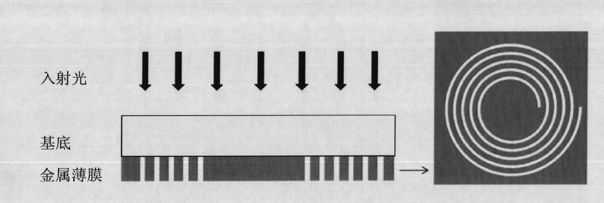
[0028] According to one embodiment of the present invention, a plasma slab lens is provided. Such as figure 1 As shown, the plasma flat lens includes a light-transmitting substrate (ie base) and a metal thin film fabricated on the substrate. A helical structure is processed on the metal film. figure 1 Among them, the left figure is the front view of the flat lens of this embodiment, and the right figure is the bottom view of the flat lens. The front view clearly shows the hierarchical structure of the flat lens of this embodiment, and shows the incident direction of light, and the bottom view clearly shows the helical structure on the metal film.

[0029] In this embodiment, it is required that the material of the substrate must have good light transmittance, and must also be a stable and reliable material capable of withstanding a certain laser powe...


PUM

PropertyMeasurementUnit
Seam widthaaaaaaaaaa
Thicknessaaaaaaaaaa
Wavelengthaaaaaaaaaa

Abstract

The invention provides a plasma slab lens which comprises a light-permeable substrate and a metal film made on the light-permeable substrate, wherein the metal film is provided with a levorotatory or dextrorotatory helical structure; the helical structure meets the condition that Phi is greater than or equal to 0 but is less than or equal to 2pi, wherein n is equal to 1, 2, 3...; k is equal to 1,2, 3...; rn (Phi) is a distance from a phase Phi of the No. n circle of the helical structure to the center in a polar coordinate; rn0 is the shortest distance from each circle of the helical structure to the center; and lambda sp is a wavelength of the surface plasma of the metal film. A preparing process of the plasma slab lens is compatible with an existing process, is easy to integrate and islow in cost. The center of a light source needs not be aligned with the center of the lens structure and the plasma slab lens can be more conveniently and simply used and can be easily made into a lens array; the plasma slab lens can break through a diffraction limit and has a huge focus depth; and the field intensity at a focal point can be controlled by adjusting the shape and size of the helical structure.

Description

technical field [0001] The invention relates to the technical field of surface plasmon excitation and near-field focusing, in particular, the invention relates to a plasma flat lens and a near-field focusing method thereof. Background technique [0002] With the development of waveguide and optical communication, the requirements for information processing ability are getting higher and higher, and the requirements for precision are also getting higher and higher, which makes optical devices develop in the direction of miniaturization and integration. However, the resolution of traditional optical systems is limited by the diffraction limit. It is difficult to greatly improve the resolution simply by increasing the numerical aperture. The focusing of near-field light developed in recent years can effectively break through the diffraction limit and realize Super-resolution focus size. [0003] Near-field focusing is achieved by utilizing surface plasmon interactions of noble...

Claims


Application Information

Patent Timeline
IPC IPC(8): G02B3/00G02B27/28
Inventor 苗俊杰刘前王永胜
Owner THE NAT CENT FOR NANOSCI & TECH NCNST OF CHINA
Why Eureka
Try Eureka