Air compressor, and flow control method for an air compressor

A technology of gas compressors and control components, which is applied in pump control, machine/engine, liquid fuel engine, etc. It can solve the problems of inability to completely close the impeller outlet, stall and surge limitations, and expand the controllable maximum flow range , Ease of making and assembling parts, and simplifying the structure of the mechanism

Inactive Publication Date: 2012-02-01
AIRZEN
View PDF5 Cites 10 Cited by
  • Summary
  • Abstract
  • Description
  • Claims
  • Application Information

AI Technical Summary

Problems solved by technology

[0005] However, the existing variable diffuser cannot completely close the outlet of the impeller, which will allow the gas to flow back through the space between the impeller and the variable diffuser, so there are limitations to the prevention of stall and surge
Moreover, the existing variable diffuser has limitations on the flow control range, and the maximum flow range that can be controlled by the existing variable diffuser is about 45% of the rated flow

Method used


Image

  • Air compressor, and flow control method for an air compressor
  • Air compressor, and flow control method for an air compressor
  • Air compressor, and flow control method for an air compressor

Examples


Embodiment Construction

[0057] Hereinafter, embodiments of the present invention will be described in detail with reference to the accompanying drawings, so that those skilled in the art can easily implement them. The present invention can be implemented in various forms, and is not limited to the following examples.

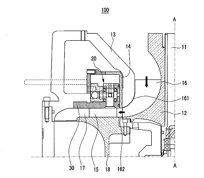
[0058] figure 1 is a partial sectional view of the gas compressor 100 according to the first embodiment of the present invention.

[0059] Please refer to figure 1 , the gas compressor 100 of the first embodiment includes: a rotating shaft 11, an impeller 12, a shroud 13, an annular valve 14, a plurality of vanes 15 ( figure 1 One fin is shown in ) and actuator 20. figure 1 The gas compressor 100 shown is bilaterally symmetrical with respect to the center line (A-A line) of the rotary shaft 11 .

[0060] The impeller 12 is fixed to the rotary shaft 11, and the rotary shaft 11 is coupled to a not-shown motor rotary shaft. A plurality of curved and radial blades 16 are formed on the...


PUM


Abstract

An air compressor having a variable diffuser system for suppressing a compressor stall and surge is provided. The air compressor comprises: i) an impeller which is fixed at a rotary shaft, and the outer surface of which has a plurality of blades each including a wing part and an edge part; ii) a shroud which covers the wing part; iii) a ring valve which is installed on a path of the diffuser, connected to an outlet of the impeller, and which moves in the direction parallel to the rotary shaft to open and shut the path of the diffuser; iv) a plurality of vanes installed at the outer surface of the ring valve on the path of the diffuser, along the circumferential direction of the path of the diffuser; and v) an actuator which is coupled to the ring valve and to the vanes to sequentially control the movement of the ring valve and the rotating angle of the vanes.

Description

technical field [0001] The present invention relates to a gas compressor, more particularly to a diffuser channel (diffuser channel) connected to the outlet of the impeller (impeller) to prevent stall and surge (surge). A variable diffuser system (diffuser system) and a flow control method of a gas compressor utilizing the system. Background technique [0002] Conventional gas compressors flow gas through a rotating impeller, which accelerates and compresses the gas using the centrifugal compression force of the impeller. The diffuser channel is connected to the outlet of the impeller to reduce noise and improve the air supply efficiency, and to decelerate the high-speed and high-pressure gas discharged from the impeller to convert the kinetic energy of the gas into pressure energy. [0003] If the gas flow through the impeller decreases or the pressure difference between the impeller inlet and outlet decreases, the gas flow becomes unstable. As a result, reverse flow occu...

Claims


Application Information

Patent Timeline
Patent Type & Authority Applications(China)
IPC IPC(8): F04D29/44F04D29/46F04D27/02F04D29/42
CPCF04D29/462
Inventor 郑奎玉郑现旭郑晋旭
Owner AIRZEN
Why Eureka
Try Eureka