Rotor blade adopting flat design

A technology of rotor blades and blades, applied in the directions of rotorcraft, motor vehicles, aircraft, etc., can solve the problems of a lot of manual work, low degree of automation, centralized cost, etc., and achieve small thickness, light weight, low manufacturing cost, and large bearing capacity. Effect

Active Publication Date: 2015-06-03
AIRBUS HELICOPTERS DEUT GMBH
View PDF3 Cites 0 Cited by
  • Summary
  • Abstract
  • Description
  • Claims
  • Application Information

AI Technical Summary

Problems solved by technology

This makes automation low and requires a lot of manual work and leads to cost concentration and error prone

Method used


Image

  • Rotor blade adopting flat design
  • Rotor blade adopting flat design
  • Rotor blade adopting flat design

Examples


Embodiment Construction

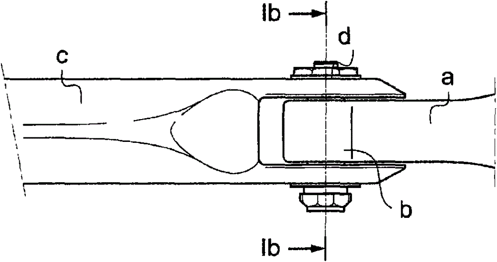
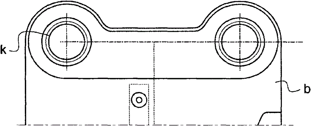
[0023] Figures 1a-c illustrate the prior art. To this end, FIG. 1 a shows a part of the rotor system at the point where the rotor blades are connected. The immediately recognizable blade part a transitions into the connecting part b in which the ring connection is formed. This forms the interface with the drive c, which surrounds the connection part b in a fork shape. Bolt d connects device c to connection part b.

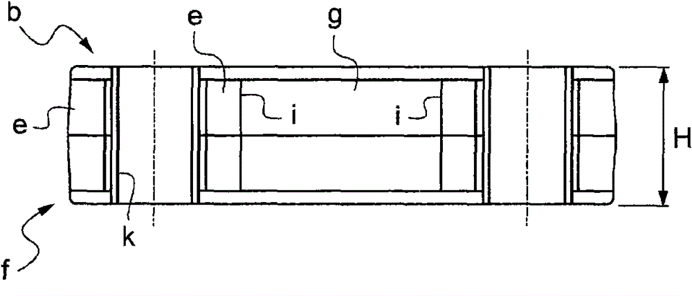
[0024] FIG. 1 b shows a sectional view according to FIG. 1 a in the region of the bolt d. The blade section consists of loops of glass fibers called rovings. A roving e is wound into a loop f around a wound fiber lining k. In the sectional view of FIG. 1 b , the plane of the roving e therefore extends parallel to the axial direction of the bolt d and lining k or perpendicular to the plane of extension of the connection part b. They form a "standing" loop f which imparts a height H to the connecting portion b. Between them is a central space g filled with hori...


PUM


Abstract

The invention particularly provides a rotor blade (1) for the main rotor of a rotary-wing aircraft, which is made of fiber reinforcement plastic. The rotor blade (1) comprises a blade part (10) and a connecting part (12) used for fixing the rotor blade (1) on a driving device (18); the connecting part (12) comprises sleeve-shaped connecting devices (14); and the further development of the rotor blade (1) lies in that the connecting devices (14) comprise flat fiber layers (S1 to S18) which approximately extend in the extending planes of the connecting parts (12).

Description

technical field [0001] The invention relates to a rotor blade, in particular the main rotor of an autogyro or helicopter, made of fiber reinforced plastic. It comprises a blade part and a connecting part for fixing the rotor blade to the drive. The connection portion comprises a sleeve-shaped connection means and is located at the end of the rotor blade opposite the blade tip and thus faces the drive shaft. The connecting portion at least indirectly connects the rotor blade to the drive device. To this end, the connection part comprises at least one sleeve-shaped connection means, for example for a bolted connection. The rotor blade more advantageously has two sleeve-shaped connection means arranged next to each other in the plane of rotation of the blade, since the tilting moment from which the blade travels forward or caused by the inertia of the blade can be absorbed. Background technique [0002] Today, rotor blades are usually manufactured using wet or pre-preg const...

Claims


Application Information

Patent Timeline
Patent Type & Authority Patents(China)
IPC IPC(8): B64C27/46B64C27/473
Inventor G·昆特茨-费切纳E·艾采C·穆勒A·瓦格奈
Owner AIRBUS HELICOPTERS DEUT GMBH
Why Eureka
Try Eureka