Motor vehicle front part

A technology for motor vehicles and vehicle speed, which is applied to vehicle components, machines/engines, mechanical equipment, etc., and can solve problems such as increasing vehicle air resistance

Active Publication Date: 2019-12-27
DR ING H C F PORSCHE AG
View PDF8 Cites 2 Cited by
  • Summary
  • Abstract
  • Description
  • Claims
  • Application Information

AI Technical Summary

Problems solved by technology

Cooling air continues to flow backwards downstream of the heat exchanger in the body, thereby inhibiting cooling air flow and increasing vehicle air resistance

Method used


Image

  • Motor vehicle front part
  • Motor vehicle front part
  • Motor vehicle front part

Examples


Embodiment Construction

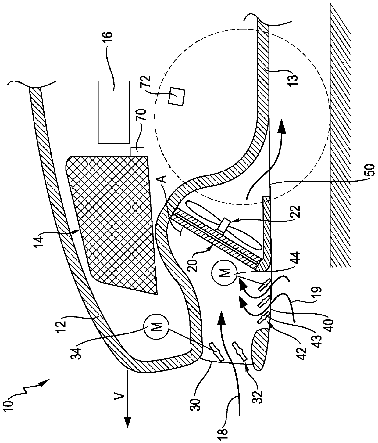
[0034] figure 1 A motor vehicle front 10 of a motor vehicle is schematically shown in longitudinal section. The outline of the front part 10 of the vehicle is defined by the vehicle body 12 within which is arranged a heat exchanger 20, a fan 22 arranged downstream of the heat exchanger 20 and driven by an electric drive motor, and a Complex cooling air installations for air supply and air discharge. The cooling air arrangement guides and controls the upper air path 18 and the lower air path 19 of the front, which can converge upstream of the heat exchanger 20 .

[0035] The cooling air device has an upper air intake opening 30 which is open substantially forward, in the opening plane of which an upper flap assembly 32 is arranged which is adjustable by a servo electric motor 34 . The upper air intake opening 30 has an upright, though not necessarily vertical, opening plane and is approximately and at least partially flush with the heat exchanger 20 in height.

[0036] The c...


PUM


Abstract

A motor vehicle front part 10 includes: a heat exchanger 20; a motorized fan 22, which is assigned to the heat exchanger 20; and a two-path cooling air arrangement for controlling the air feed to theheat exchanger 20. The cooling air arrangement includes: an upper air inlet opening 30, which opens substantially toward the front; an upper flap arrangement 32, which corresponds to the upper air inlet opening and is actuated by motor; a lower air inlet opening 40, which opens substantially toward the bottom; and a lower flap arrangement 42, which corresponds to the lower air inlet opening and isactuated by motor. The two air inlet openings 30, 40 are arranged upstream of the heat exchanger 20. A lower air outlet 50 is downstream of the heat exchanger 20 in an undertray 13 of the vehicle.

Description

technical field [0001] The invention relates to a vehicle front with a heat exchanger, an upper air path and a lower air path, both air paths leading to the heat exchanger. Background technique [0002] One such vehicle front is known, for example, from JP 201492140 A. The front of the vehicle has a cooling air unit for controlling the air supply to the heat exchanger. The cooling air device has an upper air intake opening which is open substantially forward and an upper flap assembly assigned to the upper air intake opening and which is electrically actuated. Furthermore, the vehicle front has a lower air intake opening which is substantially downwardly open and a lower flap assembly which is assigned to the lower air intake opening and is actuated electrically. Two air inlet openings are arranged upstream of the heat exchanger. The cooling air continues to flow backward downstream of the heat exchanger in the vehicle body, thereby inhibiting the flow of the cooling air,...

Claims


Application Information

Patent Timeline
IPC IPC(8): B60K11/08F01P7/10
CPCB60K11/085F01P7/10B60K11/04Y02T10/88F01P11/10F01P5/06
Inventor T·沃尔夫
Owner DR ING H C F PORSCHE AG
Why Eureka
Try Eureka