
Vehicle Pneumatic Tires

A technology for pneumatic tires and vehicles, applied in vehicle parts, tire parts, tire treads/tread patterns, etc., and can solve problems such as unconvincing

Active Publication Date: 2014-10-15
CONTINENTAL REIFEN DEUTSCHLAND GMBH
View PDF5 Cites 0 Cited by
  • Summary
  • Abstract
  • Description
  • Claims
  • Application Information

AI Technical Summary

Problems solved by technology

However, these known solutions are not yet convincing in practice

Method used


Image

  • Vehicle Pneumatic Tires
  • Vehicle Pneumatic Tires
  • Vehicle Pneumatic Tires

Examples


Embodiment Construction

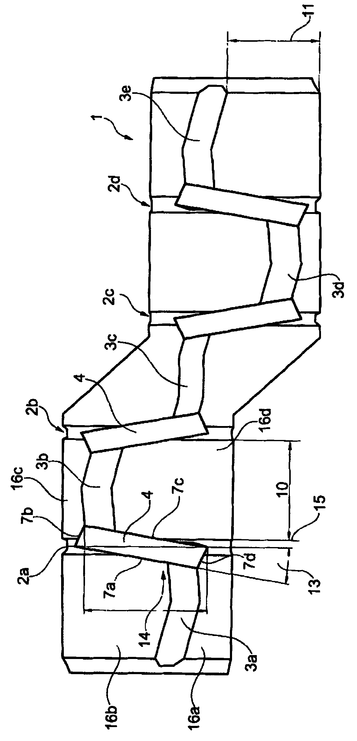
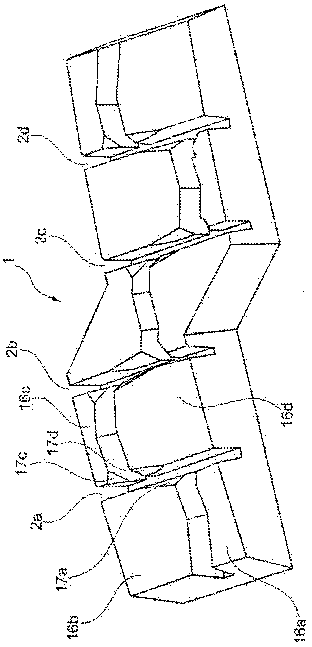
[0038] figure 1 A tread 1 of a pneumatic vehicle tire for a commercial vehicle according to the present invention is shown. The figure shows a radial sectional view of the tread 1 . Circumferential grooves 2a to 2d are arranged in the circumferential direction of the vehicle pneumatic tire. Arranged in the circumferential grooves 2a to 2d are substantially rail-shaped bodies 4 which leave a corresponding indentation in the lug. The three-dimensional rail shape 4 is integrated in a vulcanization mold by means of which the tread relief is produced in the tread. The three-dimensional track shape 4 has a depth measurement 12 which does not reach the tread base of the tread 1 .

[0039] figure 2 A plan view of a section of the tread 1 is shown. The section shows a so-called "pitch" section of the tread, wherein these sections are arranged sequentially one behind the other over the entire circumference of the pneumatic tire for vehicles. The circumferential grooves 2a, 2b, 2c...


PUM


Abstract

The invention relates to a pneumatic tire for commercial vehicles, wherein foreign objects, particularly small stones, are reliably deflected, where the block corners of each of four adjacent profile blocks (16a, 16b, 16c, 16d) are angled in a symmetrical arrangement for deflecting small stones, wherein the shape of the angled block corners (7) results from a negative imprint of a three-dimensional track-shaped body (4) disposed substantially in the longitudinal axis of the circumferential grooves (2a, 2b, 2c, 2d) between the four adjacent profile blocks.

Description

technical field [0001] The present invention relates to a vehicle pneumatic tire for a commercial vehicle. Background technique [0002] A pneumatic vehicle tire with a tread of the aforementioned technology is known from US 4,114,671 B. It is important here to optimize the grip properties of the tires in order to ensure even wear and good grip properties even with increased wear. The groove base path of the circumferential grooves of this known tread runs in a distinct zigzag shape, the magnitude of which doubles corresponding to the opposite spacing of the edge edges of the circumferential grooves on the tread periphery. These triangular surfaces extend from the perimeter of the tread almost to the bottom of the grooves and are prismatic raised surfaces. Foreign bodies, especially stones, can very easily become lodged in the circumferential grooves thus formed. [0003] Numerous patent applications and patents have been devoted to implementing the circumferential groove...

Claims


Application Information

Patent Timeline
Patent Type & Authority Patents(China)
IPC IPC(8): B60C11/04B60C19/00
CPCB60C11/1384B60C11/1392B60C11/0309B60C11/042
Inventor 徐乔
Owner CONTINENTAL REIFEN DEUTSCHLAND GMBH
Learn More