Alignment support device for rotor of permanent-magnetic wind power generator and rotor bearing replacement method

A technology for wind power generators and supporting devices, which is applied in the direction of electromechanical devices, manufacturing motor generators, casings/covers/supports, etc., which can solve the problems of weakened end plate strength, poor economy, large operating space, etc., and achieve reduction Difficulty in operation, saving construction cost, and overcoming the effects of auxiliary equipment

Active Publication Date: 2013-08-07
DONGFANG ELECTRIC MACHINERY
View PDF5 Cites 0 Cited by
  • Summary
  • Abstract
  • Description
  • Claims
  • Application Information

AI Technical Summary

Problems solved by technology

[0005] The disadvantage of the horizontal inner rotor permanent magnet synchronous generator with the above structure is that it is difficult to disassemble during installation and maintenance. To control this magnetic attraction, when the stator, rotor, rotor bearing and other components are disassembled, it is easy to bump due to excessive magnetic attraction, and the operation is unsafe. At the same time, it is difficult to guarantee production efficiency and product quality
[0008] 1. The rotor bearing replacement process is cumbersome. During the disassembly process, the generator end cover needs to be removed first. After the replacement is completed, the generator end cover should be installed again. The entire replacement process requires a large operating space; the use of stainless steel The centering of the wedge-shaped pad needs to be fine-tuned continuously in the later stage of replacement, and the efficiency is low
[0009] 2. Since the generator end cover is one of the supports supporting the shaft bearing, when the generator end cover is removed, the stainless steel wedge-shaped spacer can only play the role of passively cushioning the rotor, and the stainless steel wedge-shaped spacer cannot actively support Its rotor, so after the generator cover is removed, it will have a great influence on the force and positioning of the rotor
[0010] 3. To replace the rotor bearing with the above-mentioned centering support device, a variety of related equipment is required. For example, when disassembling the generator cover, it is necessary to load small hoisting equipment in the engine room, which is economical;
[0011] 4. Since the generator end cover usually needs to be provided with multiple measurement air gap holes, the strength of the end plate at the measurement air gap hole is weakened, and it is easily deformed and damaged when bearing the rotor weight and external impact load

Method used


Image

  • Alignment support device for rotor of permanent-magnetic wind power generator and rotor bearing replacement method
  • Alignment support device for rotor of permanent-magnetic wind power generator and rotor bearing replacement method
  • Alignment support device for rotor of permanent-magnetic wind power generator and rotor bearing replacement method

Examples


Embodiment 1

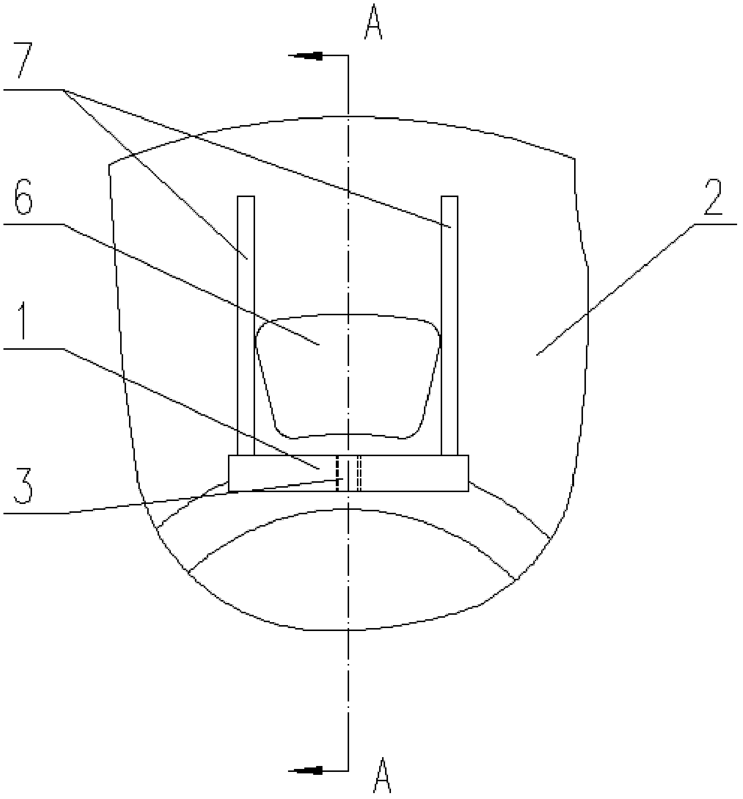
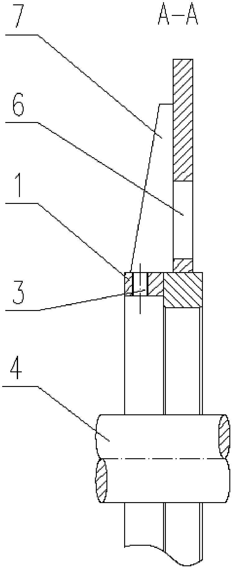
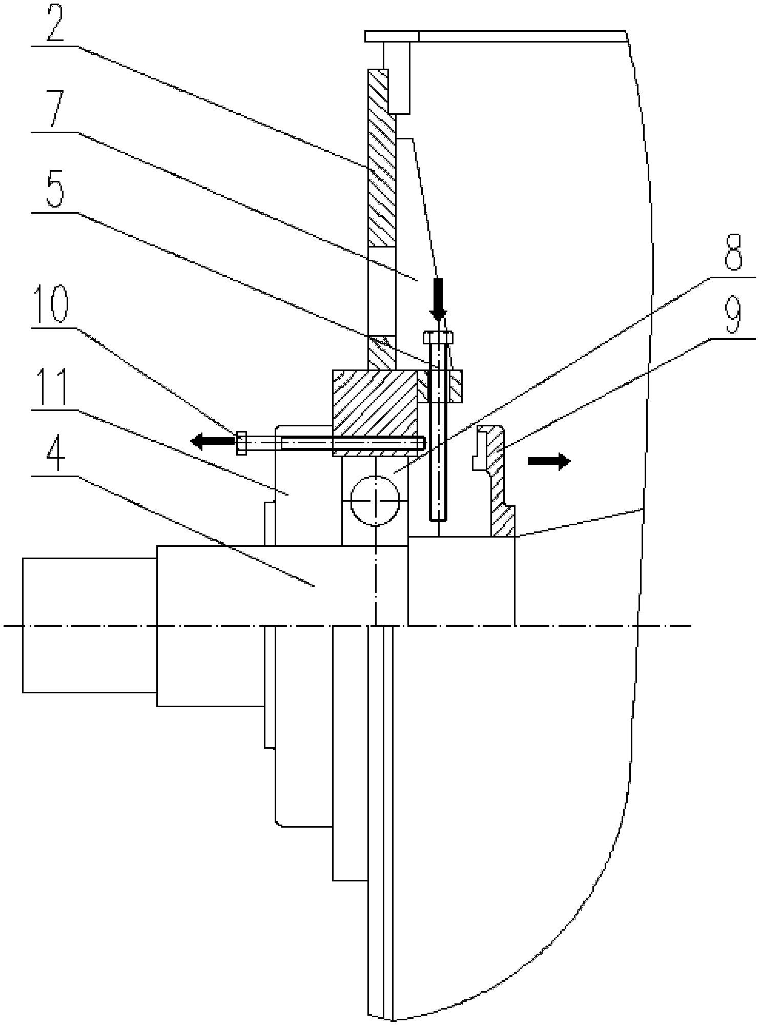
[0058] Such as Figure 1 to Figure 3 As shown, a centering support device for a permanent magnet wind turbine rotor in the present invention includes at least three centering supports, and each centering support includes a support plate 1 and a support bolt 5, wherein the support plate 1 is fixed On the generator end cover 2, the support plate 1 is provided with a threaded hole 3 penetrating the support plate 1 in the radial direction of the generator rotating shaft 4, and the threaded hole 3 is provided with a support bolt 5 adapted thereto. The support bolt 5 The bottom end of the can be in contact with the outer surface of the generator rotating shaft 4.

[0059] After the support bolts 5 are evenly tightened on the support plate 1, the end of the threaded section of the support bolt 5 is in contact with the outer surface of the generator shaft 4. At this time, the support bolts 5 on the three support plates 1 are used to pass through the 1 Screw-connected support bolts 5....

Embodiment 2

[0067] Such as Figure 1 to Figure 3 As shown, a centering support device for a permanent magnet wind turbine rotor in the present invention includes three measuring air gap holes 6 and a centering support, and the threaded hole 3 of any one of the three centering supports. The hole shafts are arranged in the vertical direction of the generator shaft 4, and the remaining two centering supports among the three centering supports are symmetrically arranged on both sides of the generator shaft 4 along the vertical direction.

[0068] That is, taking the axis center line of the generator shaft 4 as the X axis, the center of one of the measuring air gap holes 6 is set on the XZ plane, and the other two measuring air gap holes 6 are mirror symmetrically set with respect to the XZ plane. The side of the air gap hole 6 adjacent to the generator shaft 4 is provided with a support plate 1, the number of the support plate 1 is the same as the number of the measurement air gap hole 6, the...

Embodiment 3

[0078] Such as Figure 1 to Figure 3 As shown, the centering support device of a permanent magnet wind power generator rotor in the present invention includes four centering supports and measuring air gap holes 6, and the axis line of the generator shaft 4 is the X axis, then four The measuring air gap holes 6 are respectively arranged in four quadrants of the plane Cartesian coordinate system formed by the X axis and the Z axis, that is, the four measuring air gap holes 6 are all arranged in non-vertical and non-horizontal positions. The structure can apply force to the rotor more evenly and in a balanced manner, avoiding the phenomenon of uneven force caused by excessive local force on the rotor due to its own weight in the vertical direction, and too small force on the remaining parts of the magnetic attraction force. The four measuring air gap holes 6 are provided with supporting plates 1 on one side adjacent to the generator shaft 4, the number of supporting plates 1 is the...


PUM


Abstract

The invention discloses an alignment support device for a permanent-magnetic wind power generator. The alignment support device comprises at least three alignment support parts. Each alignment support part comprises a support plate and a support bolt, wherein the support plate is fixedly arranged on an end cover of the generator; a threaded hole is formed in the support plate, and penetrates through the support plate along the radial direction of a rotating shaft of the generator; the bolt is arranged on the threaded hole; and the bottom end of the bolt can contact the outer surface of the rotating shaft of the generator. A certain number of bolts fix the rotor by taking the end cover of the generator as a support to make the rotor always in an acting force balanced state, so that the rotor is prevented from being attracted onto or colliding with a stator under the action of gravity and magnetic attraction force in operation such as the replacement of a rotor bearing and the like; compared with the prior art in which the stator and the rotor are supported by stainless steel wedged cushion blocks, the rotor support device adopting the bolts has a simple structure, and is convenientto assemble and disassemble; and the bolts have small volumes, so that a large operating space can be provided for subsequent procedures.

Description

technical field [0001] The invention relates to a centering support device and a method for replacing parts by using the device, in particular to a centering support device for a rotor of a permanent magnet wind power generator and a method for replacing a rotor bearing by using the device. Background technique [0002] In the field of renewable energy, wind power technology is relatively mature, with lower development costs, and can greatly reduce carbon dioxide emissions. It has developed rapidly all over the world. At present, the main wind power technologies include asynchronous wind power technology, electric excitation synchronous wind power Power generation technology, permanent magnet synchronous wind power generation technology and so on. [0003] The permanent magnet wind generator is mainly composed of stator, rotor, generator end cover and rotor bearing and other components. The rotor bearing and generator end cover connect and assemble the stator and rotor of th...

Claims


Application Information

Patent Timeline
Patent Type & Authority Patents(China)
IPC IPC(8): H02K5/00H02K15/00
Inventor 李春娟齐智镝李松田段志强赵长青叶志伟
Owner DONGFANG ELECTRIC MACHINERY
Why Eureka
Try Eureka