Pressure flow regulator

A technology of flow regulator and pressure regulation, which is applied in the direction of respiratory protection devices, fire rescue, life-saving equipment, etc., and can solve the problems of suffocation, the regulator can not automatically adjust the volume, etc.

Inactive Publication Date: 2012-07-18
CHONGQING ANYI COAL MINE EQUIP
View PDF6 Cites 2 Cited by
  • Summary
  • Abstract
  • Description
  • Claims
  • Application Information

AI Technical Summary

Problems solved by technology

Commonly used regulators cannot automatically adjust the volume of gas entering the airbag per unit t

Method used


Image

  • Pressure flow regulator
  • Pressure flow regulator

Examples


Embodiment Construction

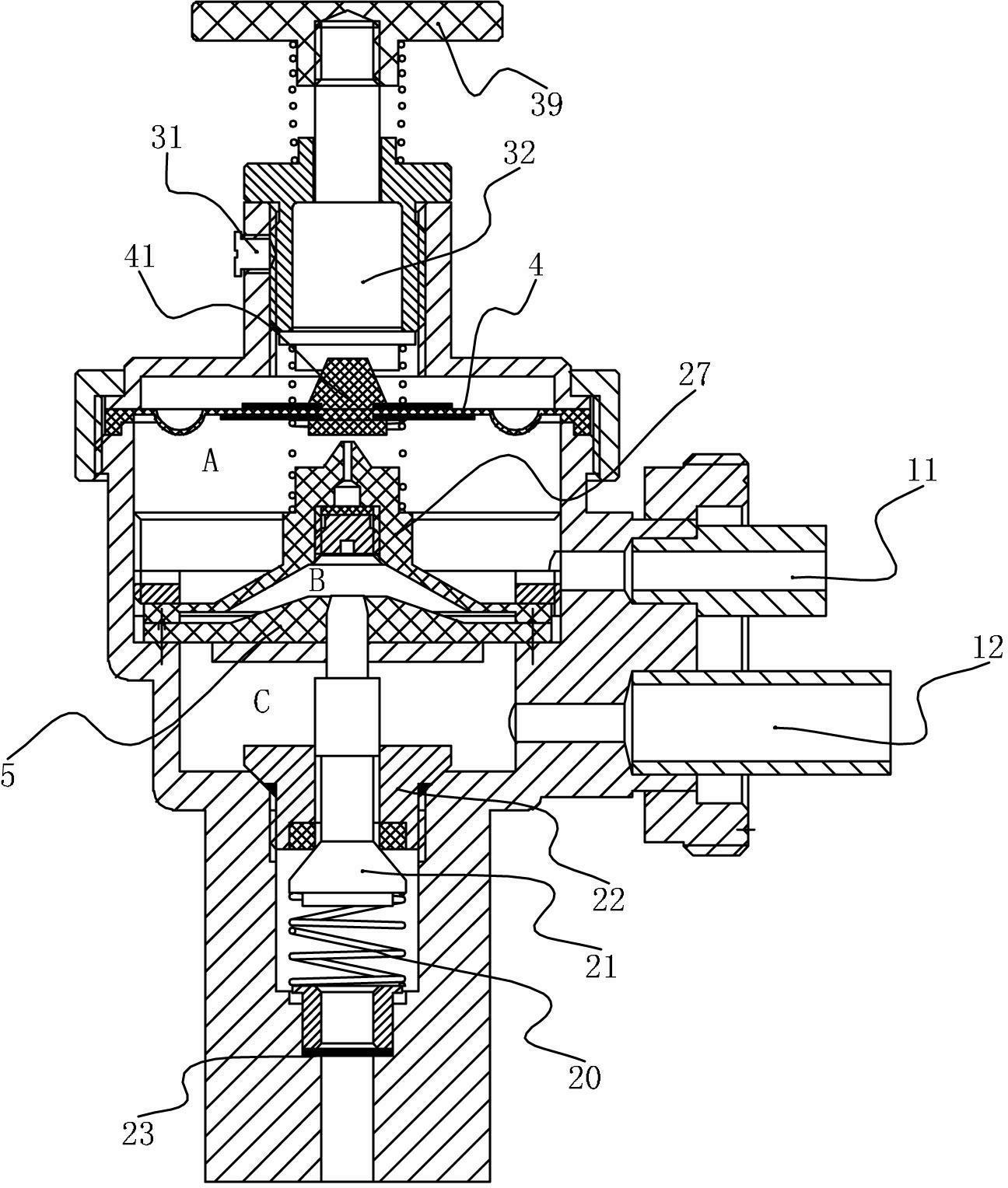
[0010] Such as figure 1 As shown, the pressure flow regulator includes an inlet valve connected to the source of breathing gas, and an outlet valve for connecting to the airbag to provide breathing gas to the user. A pressure regulating chamber is formed between the inlet valve and the outlet valve. The pressure A low-pressure diaphragm group 4 and a high-pressure diaphragm group 5 are fixedly connected in the regulating chamber, and a high-pressure chamber C is formed between the high-pressure diaphragm group 5 and the intake valve, and is connected to the outlet valve through a high-pressure outlet 12; A low-pressure chamber A is formed between the diaphragm group 4 and the high-pressure diaphragm group 5, and is connected to the outlet valve through a low-pressure air outlet 11; a diaphragm chamber B is formed in the high-pressure diaphragm group 5; the intake valve includes a connection The normally open air inlet of the diaphragm chamber and the supply inlet valve connect...


PUM


Abstract

The invention discloses a pressure flow regulator, which belongs to components of respiratory protective devices or respiratory devices. A high-pressure cavity, a low-pressure cavity and a diaphragm cavity are disposed inside a regulator, and the purpose of automatic air supply is achieved by means of controlling deformation of a diaphragm by the aid of negative pressure generated by a breather. The pressure flow regulator has the advantages that the volume of air which enters an air sac within unit time can be automatically regulated according to inspiration capacity of a wearer, the purpose of automatically regulating the inspiration capacity is achieved, and the sensation of asphyxia of the wearer is prevented.

Description

technical field [0001] The invention relates to a respiratory protection device or a component of a respiratory device, in particular to a pressure flow regulator used with a respirator. Background technique [0002] A self-contained breathing apparatus is a device intended for breathing in an immediate threat to life and health. For example, it is worn by users in mines. The respirator typically has a harness that houses an air reservoir connected to the mask. The air storage tank is equipped with high-pressure (2200psi~4500psi) air or oxygen, and is connected with a pressure reducer, which reduces the pressure, and then enters the airbag through the regulator for the wearer to breathe. The main function of the regulator is to control the airflow rate between the reservoir and the mask. Commonly used regulators cannot automatically adjust the volume of gas entering the airbag per unit time, and often cause a sense of suffocation when the wearer needs a large amount of ai...

Claims


Application Information

Patent Timeline
IPC IPC(8): A62B7/02A62B9/02
Inventor 周业海李诗军
Owner CHONGQING ANYI COAL MINE EQUIP
Why Eureka
Try Eureka