Axial flow fan and blower using same

An axial-flow and blower technology, applied in the field of axial-flow fans and blowers, can solve problems such as incompleteness, and achieve the effect of small changes in strength and smooth flow

Active Publication Date: 2016-08-03
TWINBIRD CORP
View PDF10 Cites 0 Cited by
  • Summary
  • Abstract
  • Description
  • Claims
  • Application Information

AI Technical Summary

Problems solved by technology

If the number of blades is increased, although this problem can be alleviated to a certain extent, it is not completely

Method used


Image

  • Axial flow fan and blower using same
  • Axial flow fan and blower using same
  • Axial flow fan and blower using same

Examples


Embodiment Construction

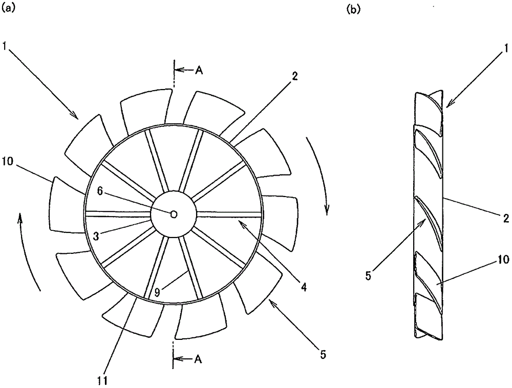
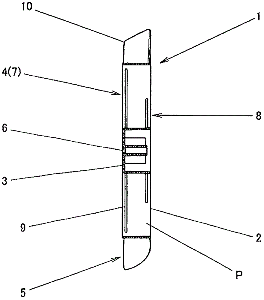
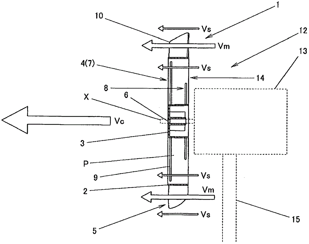
[0022] Below, according to Figure 1 ~ Figure 3 The first embodiment of the present invention will be described. Reference numeral 1 is an axial flow fan of the present invention. This axial flow fan 1 has a frame body 2 , a hub portion 3 , a spoke portion 4 , and a blade portion 5 . The frame body 2 is formed in a short cylindrical shape with both axial ends open. In addition, the hub portion 3 is located at the central portion of the frame body 2, and has an insertion hole 6 for attaching to the rotation shaft X of the motor at the center thereof. In addition, the spoke portion 4 is used to coaxially hold the hub portion 3 at the central portion of the frame body 2 . Furthermore, the above-mentioned spoke portion 4 has a front spoke portion 7 and a rear spoke portion 8, each of which is constituted by arranging a plurality of spokes 9 at equal intervals around the axial direction. In addition, the above-mentioned front spoke portion 7 and rear spoke portion 8 are stagger...


PUM


Abstract

The present invention provides an axial flow fan capable of generating a continuous air flow with little change in intensity and a blower using the axial flow fan. The axial flow fan has a short cylindrical frame body (2) with both ends open in the axial direction and a blade part (5) composed of a plurality of blades (10) arranged on the frame body (2). A circulation space ( P) makes the secondary air flow (Vs) flow in such a way that the strength of the main air flow (Vm) is moderated, so that a continuous composite air flow (Vc) with little change in strength and weakness can be obtained.

Description

technical field [0001] The present invention relates to an axial flow fan used for a blower such as a fan and a blower using the axial flow fan. Background technique [0002] Conventionally, as such an axial flow fan, an axial flow fan including a hub portion and a plurality of blade portions radially formed from the outer periphery of the hub portion is known (for example, refer to Patent Document 1). Then, by rotating such an axial flow fan with a motor, airflow is continuously generated in each blade portion, and the airflow is sent out in the axial direction as a whole. [0003] Patent Document 1: Japanese Patent Laid-Open No. 2000-110788 [0004] However, such an axial flow fan continuously generates airflow by itself if one of the blades is focused on, but the generated airflow is helical because the blades perform circular motion. In an actual axial flow fan, since the plurality of blades is provided, the helical airflow generated by each blade is shifted by the pit...

Claims


Application Information

Patent Timeline
Patent Type & Authority Patents(China)
IPC IPC(8): F04D25/08F04D29/32
Inventor 吉田胜彦佐藤隆坂井博荣
Owner TWINBIRD CORP
Why Eureka
Try Eureka