Method and device for solving contamination of boiler convection heating surface

A heating surface and boiler technology, which is applied in the field of solving the contamination of the convection heating surface of the boiler, can solve the problems that cannot be effectively solved, the convection heating surface of the boiler is easy to be contaminated, and cannot be removed, etc. low effect

Active Publication Date: 2014-08-27
DONGFANG BOILER GROUP OF DONGFANG ELECTRIC CORP
View PDF5 Cites 0 Cited by
  • Summary
  • Abstract
  • Description
  • Claims
  • Application Information

AI Technical Summary

Problems solved by technology

During the long-term operation, it was found that when the flue gas temperature of boilers burning this kind of Xinjiang high-sodium coal (such as Zhundong coal and Hami coal) is in the range of T1-T2, the convective heating surface of the boiler is most likely to be contaminated; when the flue gas temperature When it is lower than T1 or higher than T2, the contamination of the convective heating surface of the boiler can be solved by traditional steam purging method or other existing methods, which will not affect the safe operation. When the flue gas temperature is in the range of T1-T2 , the existing steam blowing method or other methods cannot effectively solve the problem. Even if multiple soot blowers are added, the contamination caused by the flue gas temperature in the T1-T2 range is still very stubborn and cannot be removed

Method used


Image

  • Method and device for solving contamination of boiler convection heating surface
  • Method and device for solving contamination of boiler convection heating surface
  • Method and device for solving contamination of boiler convection heating surface

Examples


Embodiment 1

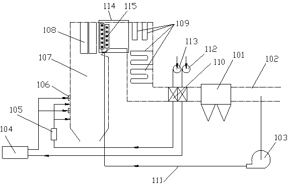
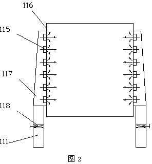
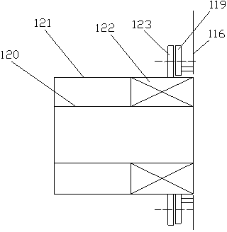
[0039] The boiler is a Π-type furnace, and the Π-type furnace includes a furnace, a flue, a dust collector, an air preheater, a primary flue gas recovery fan, a secondary flue gas recovery fan, a pulverizing device and a burner. The heating surface is set in the furnace and the tail flue, the flue gas mixing chamber is set between the furnace outlet and the tail heating surface, the air preheater is set in the flue behind the tail flue, and the primary flue gas returns to the exhaust fan and the secondary flue gas. The air return exhaust fans are respectively connected with the air preheater, and the air is sent into the air preheater to be heated to form corresponding hot primary air and hot secondary air. After entering the pulverizing device, the hot primary air enters the furnace through the burner, and heat The secondary air enters the furnace through the bellows. The flue gas mixing chamber is provided with a flue gas nozzle, and the air outlet of the flue gas return fan...

Embodiment 2

[0045] The boiler is a tower furnace, and the tower furnace includes a furnace, a flue, a dust collector, an air preheater, a primary flue gas return fan, a secondary flue gas return fan, a pulverizing device and a burner. The heating surface is divided into an upper heating surface whose flue gas temperature is lower than T1 and a lower heating surface whose flue gas temperature is higher than T2. ​​The flue gas mixing chamber is set between the upper heating surface and the lower heating surface, and the air preheater is set In the flue behind the flue, the primary flue gas return fan and the secondary flue gas return fan are respectively connected to the air preheater, and the air is sent into the air preheater to be heated to form corresponding hot primary air and hot secondary air. After the primary air enters the pulverizing device, it enters the furnace through the burner, and the hot secondary air enters the furnace through the bellows. The flue gas mixing chamber is p...

Embodiment 3

[0050] The boiler is a CFB boiler, and the CFB boiler includes a furnace, an air distribution device, a flue, a dust collector, a separator, an air preheater, a primary flue gas recovery fan, a secondary flue gas recovery fan, the outlet of the furnace and the separation The flue gas mixing chamber is set between the separator and the rear heating surface, the air preheater is set in the flue behind the tail flue, and the primary flue gas return fan and the secondary flue gas return fan are connected with the air preheater respectively. The heaters are connected, and the air is sent into the air preheater to be heated to form corresponding hot primary air and hot secondary air. The hot primary air enters the furnace through the air distribution device, and the hot secondary air enters the furnace through the bellows. The flue gas mixing chamber is provided with a flue gas nozzle, and the air outlet of the flue gas return fan is connected with the flue gas nozzle.

[0051] The ...


PUM


Abstract

The invention discloses a method and device for solving the contamination of the convective heating surface of a boiler. The boiler includes a furnace, a flue, a heating surface, a dust collector, a flue gas mixing chamber and a flue gas return exhaust fan. The flue gas mixing chamber Set in the flue with a corresponding temperature of T1-T2, the air inlet of the flue gas return fan is connected to the flue behind the dust collector, and the air outlet is connected to the flue gas mixing chamber; the method includes the following steps: the first step, at the corresponding temperature Set up a flue gas mixing chamber in the flue of T1-T2; in the second step, open an air induction hole in the flue behind the dust collector, and connect a flue gas return fan to introduce the low-temperature flue gas in the flue into the flue gas mixing chamber. The present invention designs a flue gas mixing chamber on the boiler. No heating surface is arranged in the mixing chamber. The high temperature flue gas and the low temperature flue gas are fully mixed in the mixing chamber. The flue gas temperature at the outlet of the mixing chamber is controlled to be lower than T1, and then the flue gas is introduced The internal convection heating surface can solve the problem of contamination of the heating surface, the flue gas circulation volume is easy to adjust, and the operating cost is low.

Description

technical field [0001] The invention relates to a method for solving the pollution on the convection heating surface of a boiler and a boiler utilizing the method. Background technique [0002] The safe and economical operation of power plant boilers is facing the threat of complex and changeable coal types. One of the prominent problems caused is serious ash slagging in the heating area. On biomass furnaces and power plant boilers burning some high-alkali coals, the convective heating surface staining and sticking problem induced by gaseous alkali metals has seriously affected the safety, high efficiency, and continuous operation of boilers, and has become a very important issue in the industry. insurmountable problem. [0003] my country's power plant boilers are equipped with corresponding steam soot blowing systems for blowing dust on the heating surface. The operation method of the soot blowing system is to regularly blow the heating surface Scan it again. This kind o...

Claims


Application Information

Patent Timeline
Patent Type & Authority Patents(China)
IPC IPC(8): F23J15/06F23J3/02
CPCY02E20/30
Inventor 张秀昌冉燊铭姚本荣叶恩清岳鹏飞周棋马晓伟
Owner DONGFANG BOILER GROUP OF DONGFANG ELECTRIC CORP
Why Eureka
Try Eureka