A controllable buoyancy system

A buoyancy and start-up system technology, applied to artificial islands, water rescue, ship safety, etc., can solve challenges, cost increases, restrictions, etc.

Inactive Publication Date: 2012-08-15
蒂姆・莱昂斯
View PDF5 Cites 26 Cited by
  • Summary
  • Abstract
  • Description
  • Claims
  • Application Information

AI Technical Summary

Problems solved by technology

However, this method is limited by the depth, which depends on the respective capabilities of the recovery equi...

Method used


Image

  • A controllable buoyancy system
  • A controllable buoyancy system
  • A controllable buoyancy system

Examples


Embodiment 3

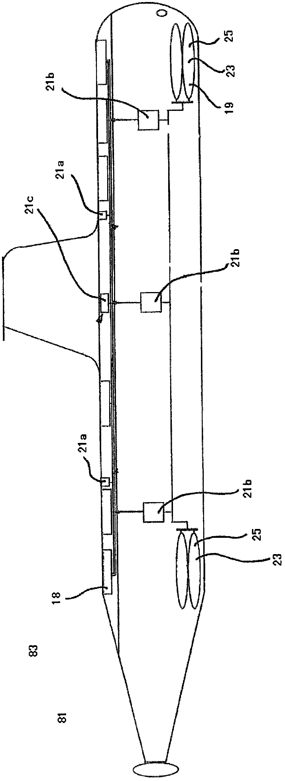
[0154] According to Embodiment 3 of the present invention, the inflation device 19 includes a gas storage system 107 . This embodiment is very similar to embodiment 2, so the same parts are given the same reference numerals. However, in this embodiment, instead of generating the gas through the medium 39, the gas is stored in a high-pressure cylinder 109, such as Figure 8 shown.

[0155] In this embodiment, the gas cylinder 109 of the gas storage system 107 has an outlet 111 which communicates with the inflatable bag 17 . Gas is kept in said cylinder 109 by three baffles 113 . Each baffle 113 is connected to a detonator 115 which, when the activation system 21 is activated, ruptures the baffle 113 so that gas can enter the inflatable bag 17 . The other detonator 115a is arranged such that its charge is directed directly to the face of said disk 113 . This structure can ensure that the baffle plate 113 is broken, and the gas can pass through.

[0156] Figure 12 The conf...


PUM


Abstract

The present system provides a buoyancy system for moving an object (401) in a body of water. The system comprises at least one inflatable body (17) which, when inflated, increases the buoyancy of the object (401), and an inflation apparatus (37) to inflate the at least one inflatable body (17). The system also comprises an activation system (21) to activate the inflation apparatus (37). Upon activation of the activation system (21) the inflation apparatus (37) causes gas to flow to the at least one inflatable body (17), causing the object (401) to move. The inflation apparatus may comprise a hydrostatic sensor (407) and pressure relief valves (91, 93) to automatically control the depth of the object and a guide wire (411) to aid locate the object on the surface.

Description

technical field [0001] The present invention relates to a buoyancy system for lifting or lowering objects in water. [0002] In one application of the invention, the buoyancy system is designed to lift malfunctioning or damaged objects, such as submarines and aircraft, from a certain depth and / or maintain them on the surface. [0003] In another application of the invention, the buoyancy system is designed to raise and / or lower objects from deep water such that they are raised and resurfaced or lowered into position. Such objects include underwater subsea infrastructure such as sub-sea trees, manifolds and platform anchors. Background technique [0004] Operations in deep water present many inherent difficulties. These problems are usually related to the pressure that increases with depth and also to the weight of infrastructure such as cables. [0005] At increasing depths, recovery of objects becomes increasingly difficult. This has been highlighted by numerous maritim...

Claims


Application Information

Patent Timeline
IPC IPC(8): B63C7/10B63G8/40E02B17/02B64D25/00B63B38/00B64C1/34E02D29/09B63C9/28B64D47/00B63B35/00
CPCB63C7/10B63G8/14B64D25/18E21B19/002
Inventor 蒂姆·莱昂斯
Owner 蒂姆・莱昂斯
Why Eureka
Try Eureka