Crystal lamp source

A crystal lamp and lamp source technology, which is applied to electric light sources, lighting devices, components of lighting devices, etc., can solve problems such as poor light refraction effect, and achieve the effect of improving light splitting effect.

Inactive Publication Date: 2012-09-05
DONGGUAN MASSTOP LIQUID CRYSTAL DISPLAY +1
View PDF7 Cites 2 Cited by
  • Summary
  • Abstract
  • Description
  • Claims
  • Application Information

AI Technical Summary

Problems solved by technology

In practical applications, after comparing the light refraction effects of the above three bulbs, it can be known that: there are multiple high-directivity light sources ( Figure 3B ) and thin line light sources ( Figure 3C ) bulbs have a better light refraction effect and can produce dazzling and colorful visual effects, while high Ra value bulbs ( Figure 3A ) light refraction effect is poor

Method used


Image

  • Crystal lamp source
  • Crystal lamp source
  • Crystal lamp source

Examples


Embodiment Construction

[0042] Other purposes and advantages of the present invention can be further understood from the technical features disclosed in the present invention. In order to make the above and other objects, features and advantages of the present invention more comprehensible, the following specific embodiments are described in detail with reference to the accompanying drawings.

[0043] The aforementioned and other technical contents, features and effects of the present invention will be clearly presented in the following detailed description of the embodiments with reference to the accompanying drawings. The directional terms mentioned in the following embodiments, such as: up, down, left, right, front or back, etc., are only directions referring to the attached drawings. Accordingly, the directional terms are used to illustrate and not to limit the invention.

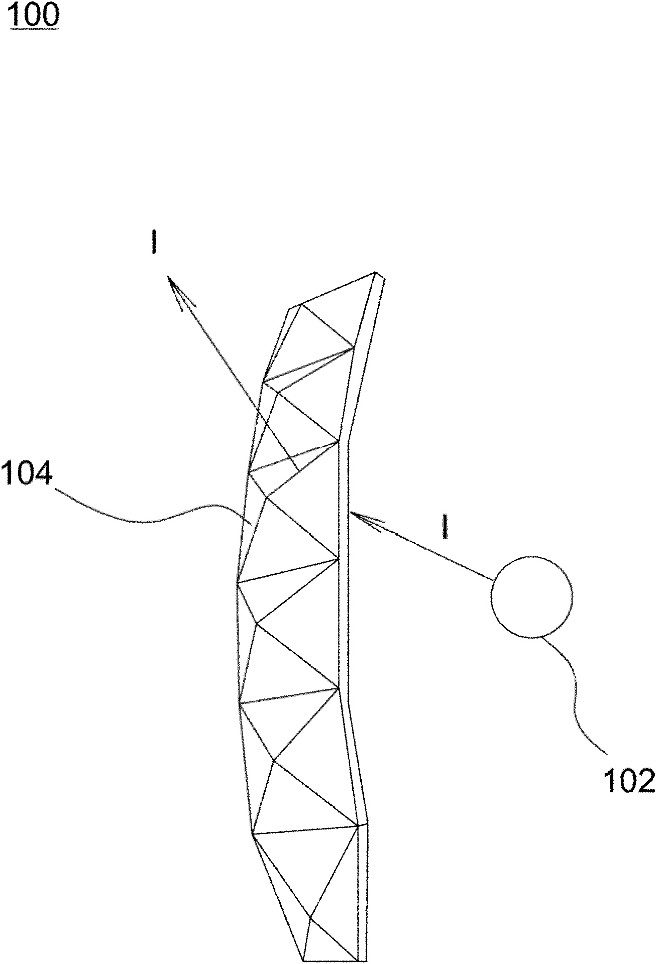
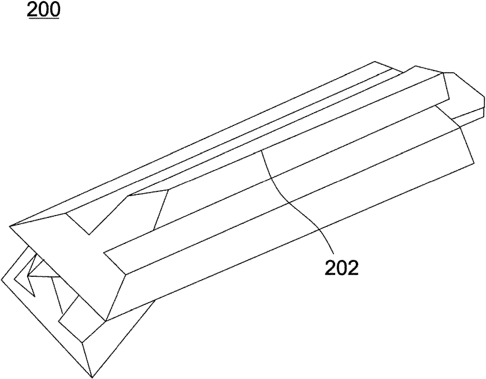
[0044] Figure 4 It is a schematic diagram of a crystal lamp light source according to an embodiment of the present invent...


PUM


Abstract

The invention provides a crystal lamp source which comprises a light guide post, a luminescence element and a linear condensation structure, wherein a ray emitted from the luminescence element enters the light guide post from the bottom surface of the light guide post; the linear condensation structure surrounds the side surface of the light guide post and reflects or refracts the ray emitted from the luminescence element to provide a fine line light source which surrounds the light guide post.

Description

technical field [0001] The present invention relates to a light source, in particular to a crystal lamp light source. Background technique [0002] Such as figure 1 As shown, the light source 102 of the existing crystal lamp 100 is distributed around a plurality of polyhedrons 104 respectively having a plurality of refracting walls. Although these polyhedrons are a kind of dispersion element, the light I emitted by the light source 102 is a light beam diverging in various directions. Moreover, the light refraction effect of only using the walls with different inclination angles to refract the light I is limited, so dazzling and colorful visual effects cannot be produced. Additionally, if figure 2 As shown, the shape of the wall surface of the crystal lamp 200 can form a thin line 202 to improve the light refraction effect, but the light refraction effect provided by this design is still limited. Furthermore, Taiwan Patent Publication No. M255922 discloses a design of for...

Claims


Application Information

Patent Timeline
Patent Type & Authority Applications(China)
IPC IPC(8): F21S2/00F21V13/00
Inventor 叶志庭黄国瑞
Owner DONGGUAN MASSTOP LIQUID CRYSTAL DISPLAY
Why Eureka
Try Eureka