Crystal lamp light source

A technology of crystal lamp and lamp source, applied in electric light source, light source fixing, lighting device and other directions, can solve the problem of poor light refraction effect, etc., and achieve the effect of improving dispersion effect

Inactive Publication Date: 2015-02-11
WINTEK CORP
View PDF5 Cites 2 Cited by
  • Summary
  • Abstract
  • Description
  • Claims
  • Application Information

AI Technical Summary

Problems solved by technology

Generally speaking, with multiple highly directional light sources ( Figure 3B ) and thin line light sources ( Figure 3C ) bulbs have a better light refraction effect and can produce dazzling and colorful visual effects, while high Ra value bulbs ( Figure 3A ) light refraction effect is poor

Method used


Image

  • Crystal lamp light source
  • Crystal lamp light source
  • Crystal lamp light source

Examples


Embodiment Construction

[0046] The aforementioned and other technical contents, features and effects of the present invention will be clearly presented in the following detailed description of the embodiments with reference to the drawings. The directional terms mentioned in the following embodiments, such as: up, down, left, right, front or back, etc., are only directions referring to the attached drawings. Accordingly, the directional terms are used to illustrate and not to limit the invention.

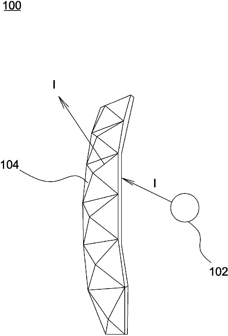
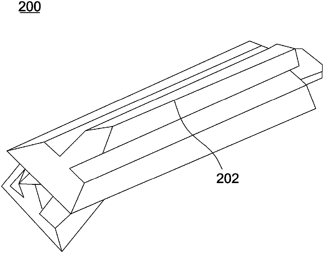
[0047] Figure 4 It is a schematic diagram of a crystal light source of an embodiment of the present invention, such as Figure 4 As shown, the crystal light source 10 includes a light guide column 12 , a base 14 and a light emitting element 16 . The light guide column 12 has a top surface 12a and a bottom surface 12b opposite to each other, and a side surface 12c connected between the top surface 12a and the bottom surface 12b. The side surface 12c is a curved surface concave toward the inside of the l...


PUM


Abstract

The invention discloses a crystal lamp light source comprising a light guide post, a light-emitting element and a groove structure. The light guide post has a top face and a bottom face opposite to each other and further has a side face connected between the top face and a bottom face; the side face is a curved face recessing towards the inside of the light guide post. The light-emitting element is disposed at a positon close to the bottom face; light emitted by the light-emitting element enters the light guide post from the bottom face. The groove structure is formed on the top face and recesses towards the inside of the light guide post. Incoming light of the light-emitting element of the crystal lamp light source can be effectively deflected into light coming out from the side, and wide-angle sidewise light emission is achieved; additionally, thin-cord light sources surrounding the side of the light guide post are of high light outgoing directionality and are distributed in different areas in space, thus light dispersion of the crystal lamp light source can be greatly improved; after the light emitted by a linear condensing structure passes a crystal polyhedron, a crystal lamp can produce flashy and colorful light.

Description

technical field [0001] The invention relates to a crystal lamp light source. Background technique [0002] Such as figure 1 As shown, the light source 102 of the existing crystal lamp 100 is distributed around a plurality of polyhedrons 104 respectively having a plurality of refracting walls. Although these polyhedrons are a kind of dispersion element, the light I emitted by the light source 102 is a light beam diverging in various directions. Moreover, the light refraction effect of only using the walls with different inclination angles to refract the light I is limited, so dazzling and colorful visual effects cannot be produced. Additionally, if figure 2 As shown, the shape of the wall surface of the crystal lamp 200 can form a thin line 202 to improve the light refraction effect, but the light refraction effect provided by this design is still limited. Furthermore, Taiwan Patent Publication No. M255922 discloses a design of forming multi-point microstructures on the s...

Claims


Application Information

Patent Timeline
Patent Type & Authority Applications(China)
IPC IPC(8): F21S2/00F21V13/00F21V17/00
CPCF21S2/00F21V13/00F21V17/00
Inventor 叶志庭林明传
Owner WINTEK CORP
Why Eureka
Try Eureka