

Constant directivity acoustic horn
- Summary
- Abstract
- Description
- Claims
- Application Information
AI Technical Summary
Benefits of technology
Problems solved by technology
Method used
Image

Examples
first embodiment
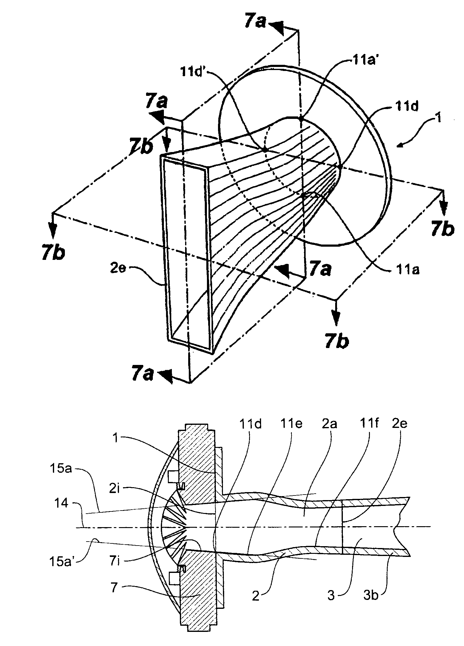
[0058]Referring now to FIG. 7, the invention is shown. It can be seen that a pair of opposite profiles of the internal surface of the throat 2, lying within a plane indicated in dotted outline and marked 7b—7b—7b—7b, initially diverge in a direction from the throat entrance towards the throat exit. This divergence, clearly illustrated by tangent lines 15a and 15a′ in FIG. 7b is in marked contrast to the convergence shown by tangent lines 15d and 15d′ in FIG. 6b.
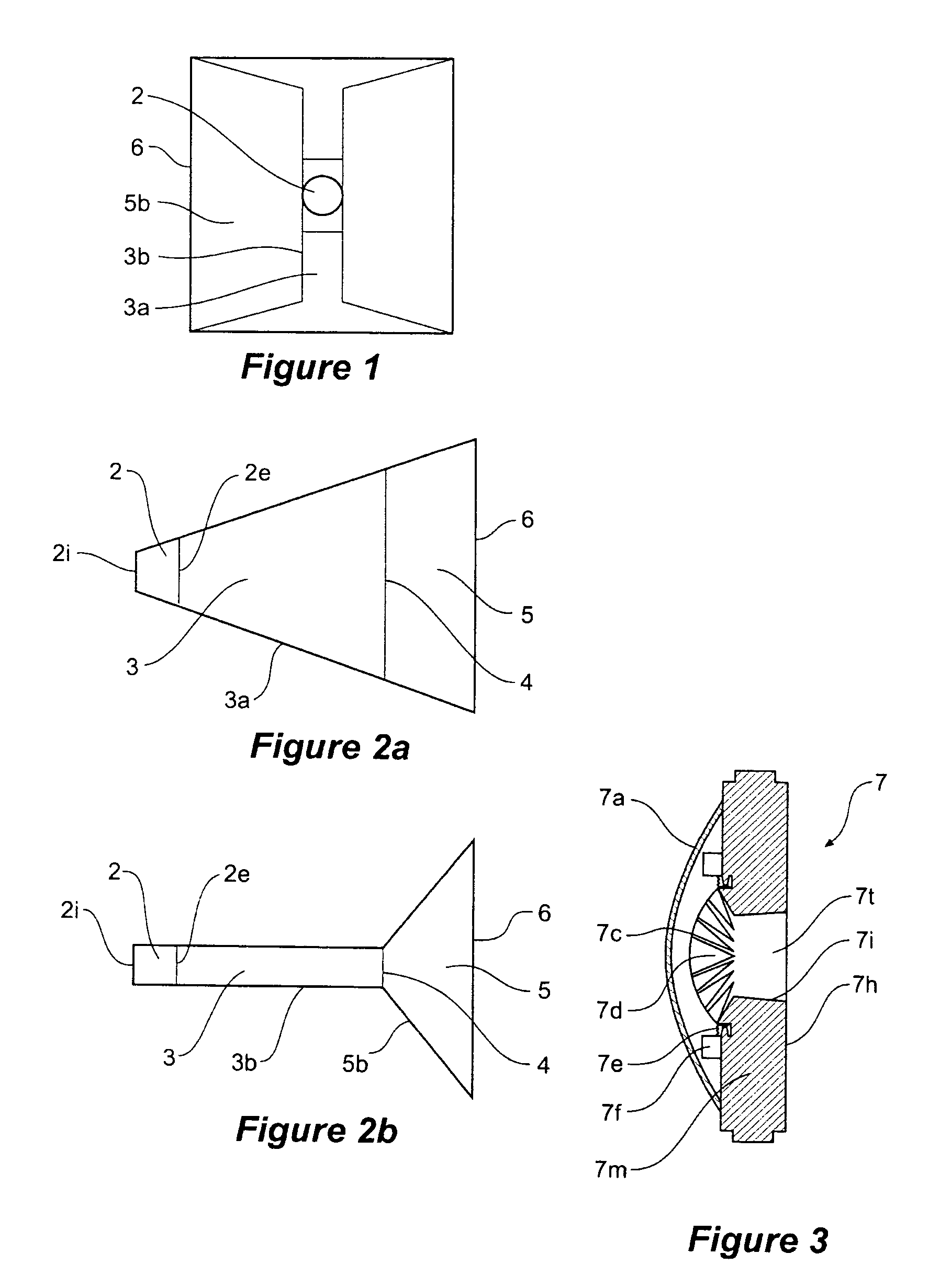
[0059]FIGS. 7a and 7b show cross-sectional views of the first embodiment of the invention at planes 7a—7a—7a—7a and 7b—7b—7b—7b (shown in FIG. 7). Referring to the vertical profile cross-sectional view of FIG. 7a, the source driver unit 7 is attached to the flange 1 and passes acoustic energy into the throat entrance 2i and through the round to rectangular transition region 2a into the feeder region 3. The profile of the first pair of walls or wall portions 3a has an angle of commencement 11a which matches the exit angle 7i ...
second embodiment
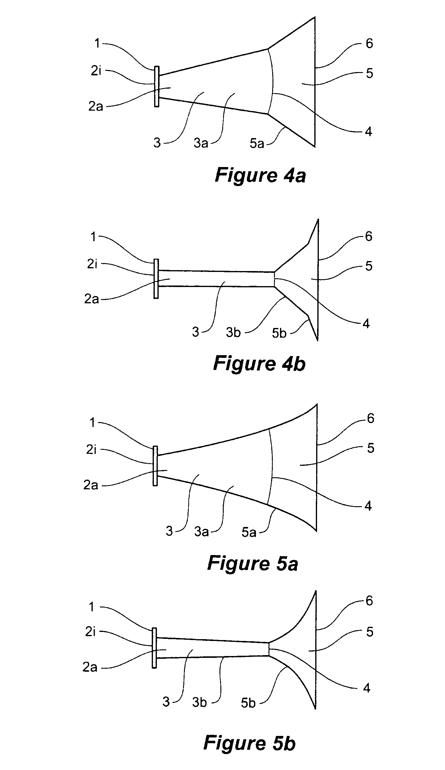
[0063]the invention is shown in FIGS. 8a and 8b. Referring to the vertical profile cross-sectional view of FIG. 8a the source driver unit 7 is again attached to the flange 1 and passes acoustic energy into the throat entrance 2i and through the round to rectangular transition region 2a into the feeder region 3. Again, the profile of the first pair of walls or wall portions 3a has an angle of commencement 11a which matches the exit angle 7i of the driver source unit. The profile smoothly changes through 11b and 11c to that desired 3a for the beam angle. The acoustic energy then passes into the feeder region 3, where the second pair of walls are substantially parallel.
[0064]With this embodiment of the invention, the profile converges / narrows to a neck having a height / width 11c, a length smaller than the exit size of the source driver unit 7, giving a better dispersion of high frequency acoustic energy into the acoustic horn.
[0065]Referring to the horizontal profile cross-sectional vie...
PUM
 Abstract
Description
Claims
Application Information