Light source for crystal lamp

A technology for crystal lamps and light sources, which is applied to electric light sources, lighting devices, components of lighting devices, etc., can solve problems such as poor light refraction effects, achieve low manufacturing costs, and improve the effects of light separation and dispersion

Inactive Publication Date: 2012-07-04
WINTEK CORP +1
View PDF5 Cites 11 Cited by
  • Summary
  • Abstract
  • Description
  • Claims
  • Application Information

AI Technical Summary

Problems solved by technology

In practical applications, after comparing the light refraction effects of the above three bulbs, it can be seen that there are multiple high-directivity light sources ( Figure 3B ) and thin line light sources ( Figure 3C ) bulbs have a better light refraction effect and can produce dazzling and colorful visual effects, while high Ra value bulbs ( Figure 3A ) light refraction effect is poor

Method used


Image

  • Light source for crystal lamp
  • Light source for crystal lamp
  • Light source for crystal lamp

Examples


Embodiment Construction

[0038] The aforementioned and other technical contents, features and functions of the present invention will be clearly presented in the following detailed description of the embodiments with reference to the drawings. The directional terms mentioned in the following embodiments, such as: up, down, left, right, front or back, etc., are only directions referring to the attached drawings. Accordingly, the directional terms are used to illustrate and not to limit the invention.

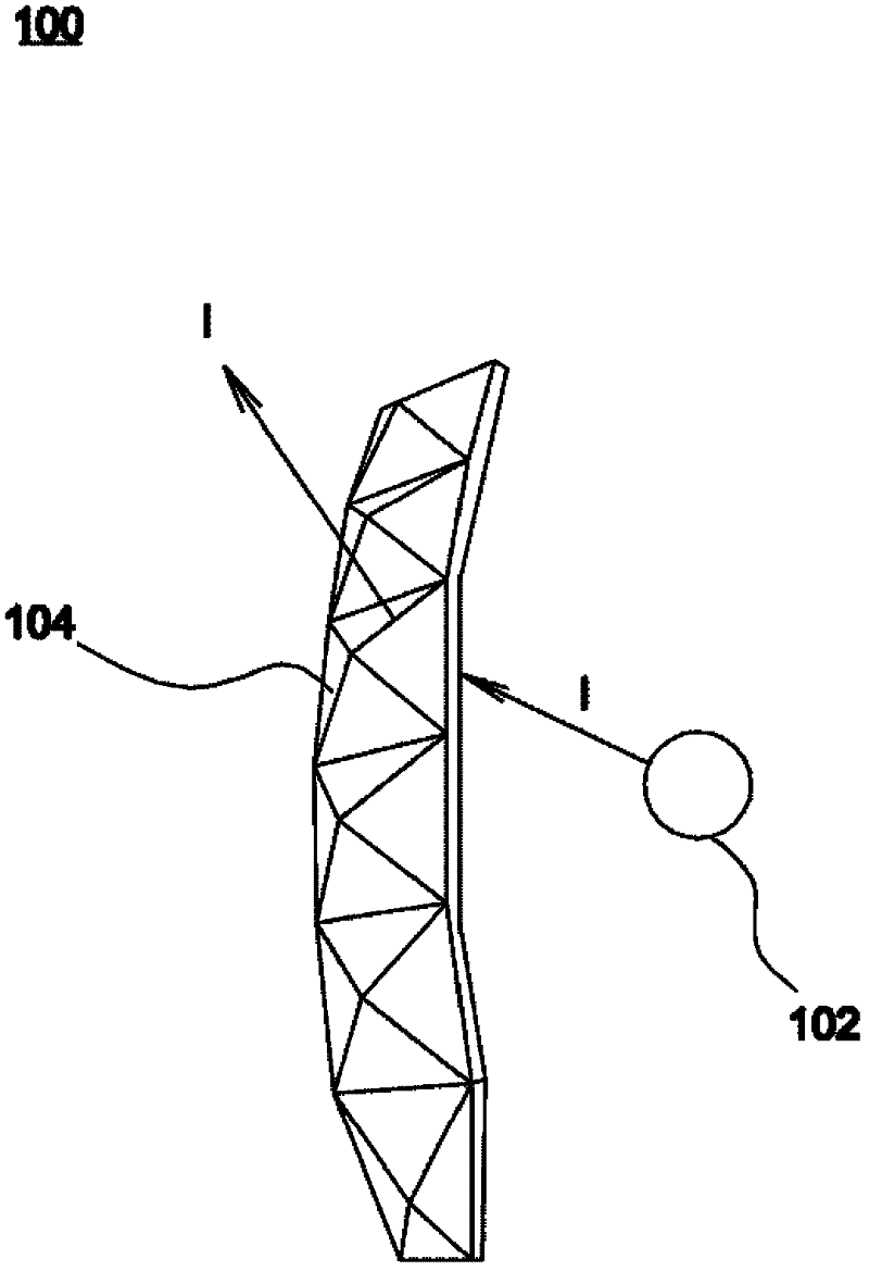
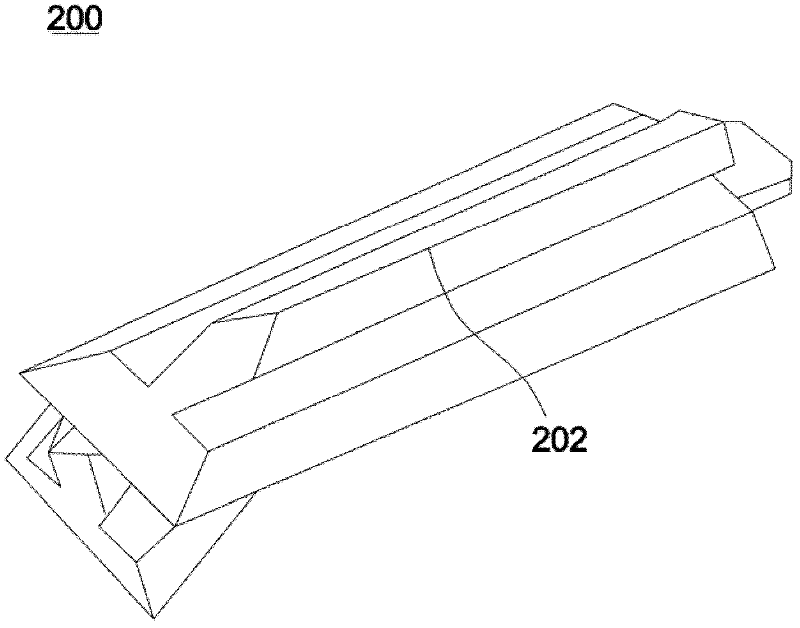
[0039] Figure 4 It is a schematic diagram of a crystal lamp light source according to an embodiment of the present invention, such as Figure 4 As shown, the crystal light source 10 includes a lens structure 12 , a plurality of prism structures 14 and a light emitting element 16 . The lens structure 12 may have a bottom surface 12a and an arc surface 12b connected to the periphery of the bottom surface 12a. In this embodiment, the arc surface 12b may connect to the entire periphery of the bottom surfa...


PUM


Abstract

The invention provides a light source for a crystal lamp which has a lens structure, at least one light-emitting element, and a plurality of prism structures. The lens structure has a bottom surface and an arc surface connected with a periphery of the bottom surface, and a notch structure is formed on the bottom surface and concave towards the inside of the lens structure. The light-emitting element is disposed inside the notch structure, and the prism structures are formed on the arc surface. Each of the prism structures deflects the light emitted by the light-emitting element and passing through the arc surface of the lens structure. The light source provided can enable the crystal lamp to generate colorful visual effects in a lower manufacturing cost.

Description

technical field [0001] The invention relates to crystal lamp technology, in particular to a crystal lamp light source. Background technique [0002] like figure 1 As shown, the light source 102 of the existing crystal lamp 100 is distributed around a plurality of polyhedrons 104 respectively having a plurality of refracting walls. Although these polyhedrons are a kind of dispersion element, the light I emitted by the light source 102 is a light beam diverging in various directions. Moreover, the light refraction effect of only using the walls with different inclination angles to refract the light I is limited, so dazzling and colorful visual effects cannot be produced. Additionally, if figure 2 As shown, the shape of the wall surface of the crystal lamp 200 can form a thin line 202 to improve the light refraction effect, but the light refraction effect provided by this design is still limited. Furthermore, Taiwan Patent Publication No. M255922 discloses a design of formi...

Claims


Application Information

Patent Timeline
Patent Type & Authority Applications(China)
IPC IPC(8): F21S2/00F21V5/02F21V5/04
CPCF21V5/04
Inventor 叶志庭黄国瑞
Owner WINTEK CORP
Why Eureka
Try Eureka