LED rotating projection lamp

A technology for floodlights and lamp holders, applied in the direction of light source, electric light source, light source fixation, etc., can solve the problems of restricting the light projection direction of the lamp body, reducing the applicable surface of LED floodlights, and inconvenience of LED floodlights

Active Publication Date: 2012-05-23
山东魏仕照明科技有限公司
View PDF0 Cites 1 Cited by
  • Summary
  • Abstract
  • Description
  • Claims
  • Application Information

AI Technical Summary

Problems solved by technology

If you want to adjust the lamp body on the base to realize the rotation of the lamp body on the base, you need to adjust it by turning the screw, which makes the rotation and positioning of the lamp body on the base relatively inconvenient; Among them, the lamp body can only be rotated back and forth on the base, that is to say, the lamp body cannot be rotated left and right, which brings great inconvenience to the use of LED floodlights, greatly restricts the light projection direction of the lamp body, and leads to LED floodlights cannot illuminate any place that needs to be illuminated, which greatly reduces the applicable surface of LED floodlights

Method used


Image

  • LED rotating projection lamp
  • LED rotating projection lamp
  • LED rotating projection lamp

Examples


Embodiment Construction

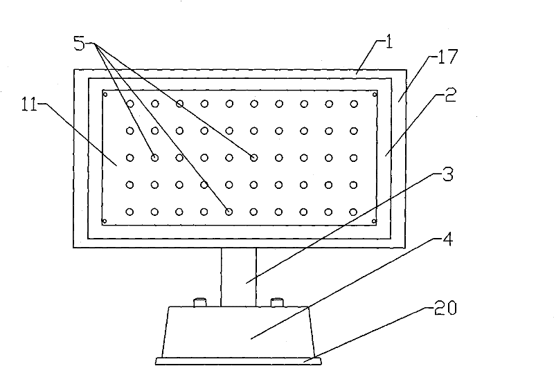
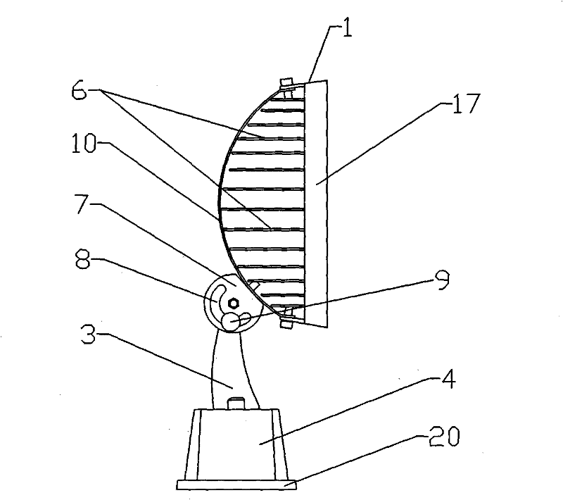
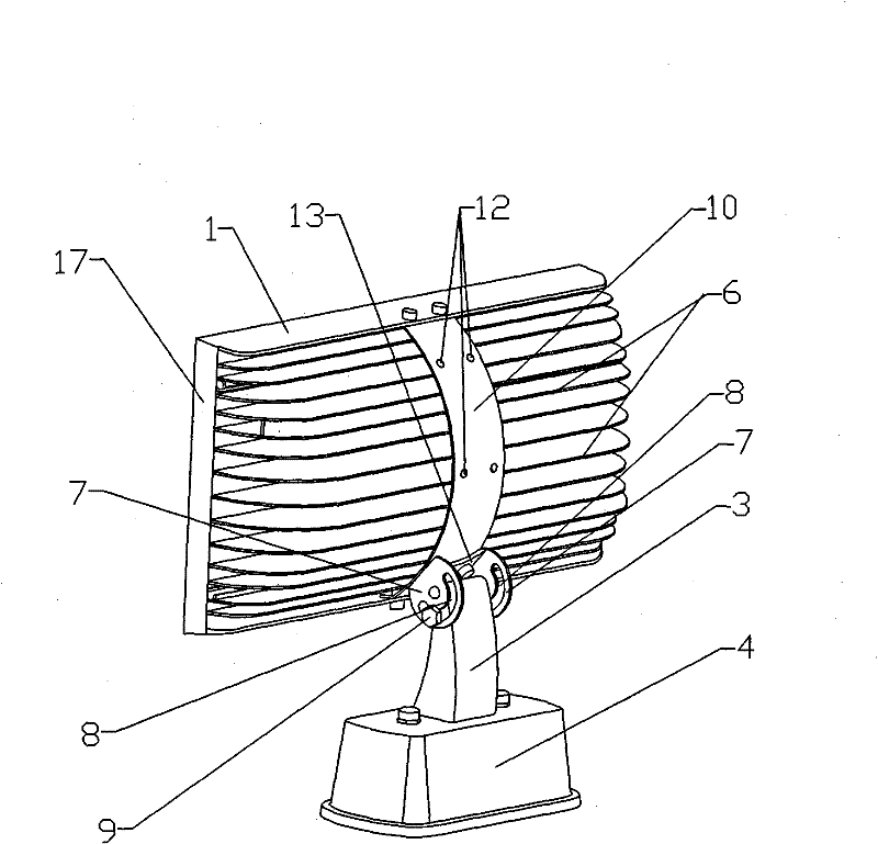
[0026] Examples such as figure 1 , figure 2 , image 3 and Figure 4 As shown in the figure, an LED turning spotlight includes a lamp base and a base 4, a connecting handle 3 is provided between the base 4 and the lamp base, and an adjusting device is provided between the connecting handle 3 and the lamp base.

[0027] The lamp cap includes a lamp cap shell 1 and a lamp cap panel 2, the upper and lower parts of the lamp cap shell 1 are respectively provided with horizontal bar-shaped fixing grooves 21, the lamp cap panel 2 is arranged between the two fixing grooves 21, and the two sides of the lamp cap panel 2 are respectively provided with Sealing aluminum strip 18, the sealing aluminum strip 18 cooperates with the lamp cap housing 1 to fix the lamp cap panel 2, the sealing aluminum strip 18 has good sealing performance, and the outer sides of the two sealing aluminum strips 18 are respectively provided with baffles 17, the baffles 17 have both Decorative effect, but also...


PUM


Abstract

The invention relates to an LED rotating projection lamp which comprises a lamp holder and a base, wherein a connecting handle is arranged between the base and the lamp holder, a regulating device is arranged between the connecting handle and the lamp holder, the regulating device comprises a support plate, the support plate is detachably connected with the lamp holder, the connecting handle is rotatably connected with the support plate, the support plate is provided with a cambered through groove, the circle center of the cambered through groove is positioned on a rotating shaft between the support plate and the connecting handle, and the lamp holder can be rotated upwards and downwards by rotating the support plate around the rotating shaft between the support plate and the connecting handle; and the base of the LED rotating projection lamp is provided with a through hole, the base is movably connected with the connecting handle, the bottom of the connecting handle is provided with an internal thread, a bolt connects the connecting handle and the base after passing through the through hole, and the lamp holder can be rotated leftwards and rightwards by rotating the connecting handle. Thus, the invention realizes the omni-directional adjustment on the LED rotating projection lamp, and enables the projection direction to better meet the requirements.

Description

technical field [0001] The invention relates to an LED floodlight, in particular to an LED turning floodlight. Background technique [0002] Currently commonly used LED floodlights include a lamp body and a base. The lamp body is fixed on the base by screws so that the lamp body can be rotated on the base so that the light emitted by the lamp body can be irradiated to a designated position. When the LED floodlight is in use, it is fixed on the outer wall of the building or on the ground through the base. If you want to adjust the lamp body on the base to realize the rotation of the lamp body on the base, you need to adjust it by turning the screw, which makes the rotation and positioning of the lamp body on the base relatively inconvenient; Among them, the lamp body can only be rotated back and forth on the base, that is to say, the lamp body cannot be rotated left and right, which brings great inconvenience to the use of LED floodlights, greatly restricts the light project...

Claims


Application Information

Patent Timeline
Patent Type & Authority Patents(China)
IPC IPC(8): F21S8/00F21V19/02F21V29/00F21Y101/02F21V29/70
Inventor 赵俊健李振威
Owner 山东魏仕照明科技有限公司
Why Eureka
Try Eureka