Buffer stop block structure and corresponding package box body

A buffer block and box technology, applied in the field of packaging, can solve problems such as high production cost and environmental pollution, and achieve the effects of low production cost, high production cost, and good buffering and fixing effect.

Inactive Publication Date: 2012-09-19
TCL CHINA STAR OPTOELECTRONICS TECH CO LTD
View PDF10 Cites 10 Cited by
  • Summary
  • Abstract
  • Description
  • Claims
  • Application Information

AI Technical Summary

Problems solved by technology

It solves the technical problems of high production cost and p

Method used


Image

  • Buffer stop block structure and corresponding package box body
  • Buffer stop block structure and corresponding package box body
  • Buffer stop block structure and corresponding package box body

Examples


Embodiment Construction

[0029] The following descriptions of the various embodiments refer to the accompanying drawings to illustrate specific embodiments in which the present invention can be practiced. The directional terms mentioned in the present invention, such as "up", "down", "front", "back", "left", "right", "inside", "outside", "side", etc., are for reference only The orientation of the attached schema. Therefore, the directional terms used are used to illustrate and understand the present invention, but not to limit the present invention.

[0030] In the figures, structurally similar units are denoted by the same reference numerals.

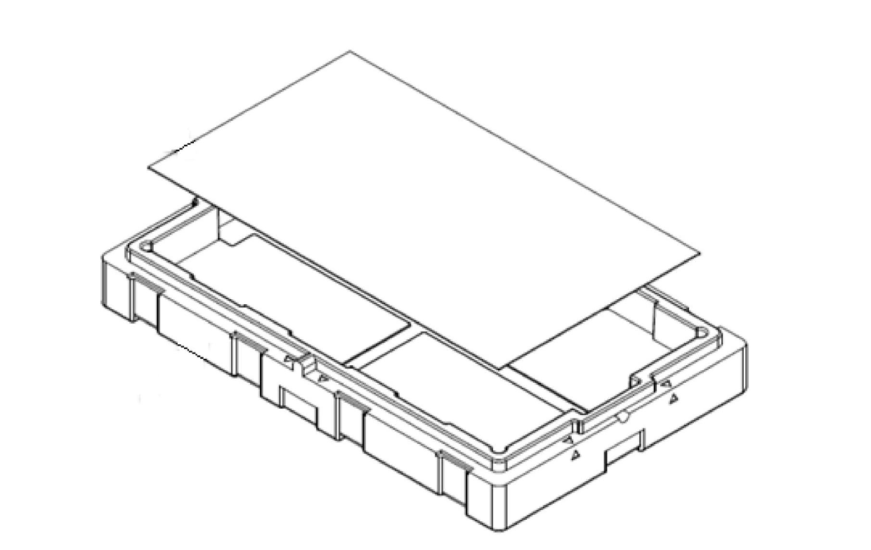
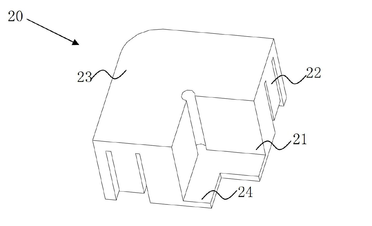
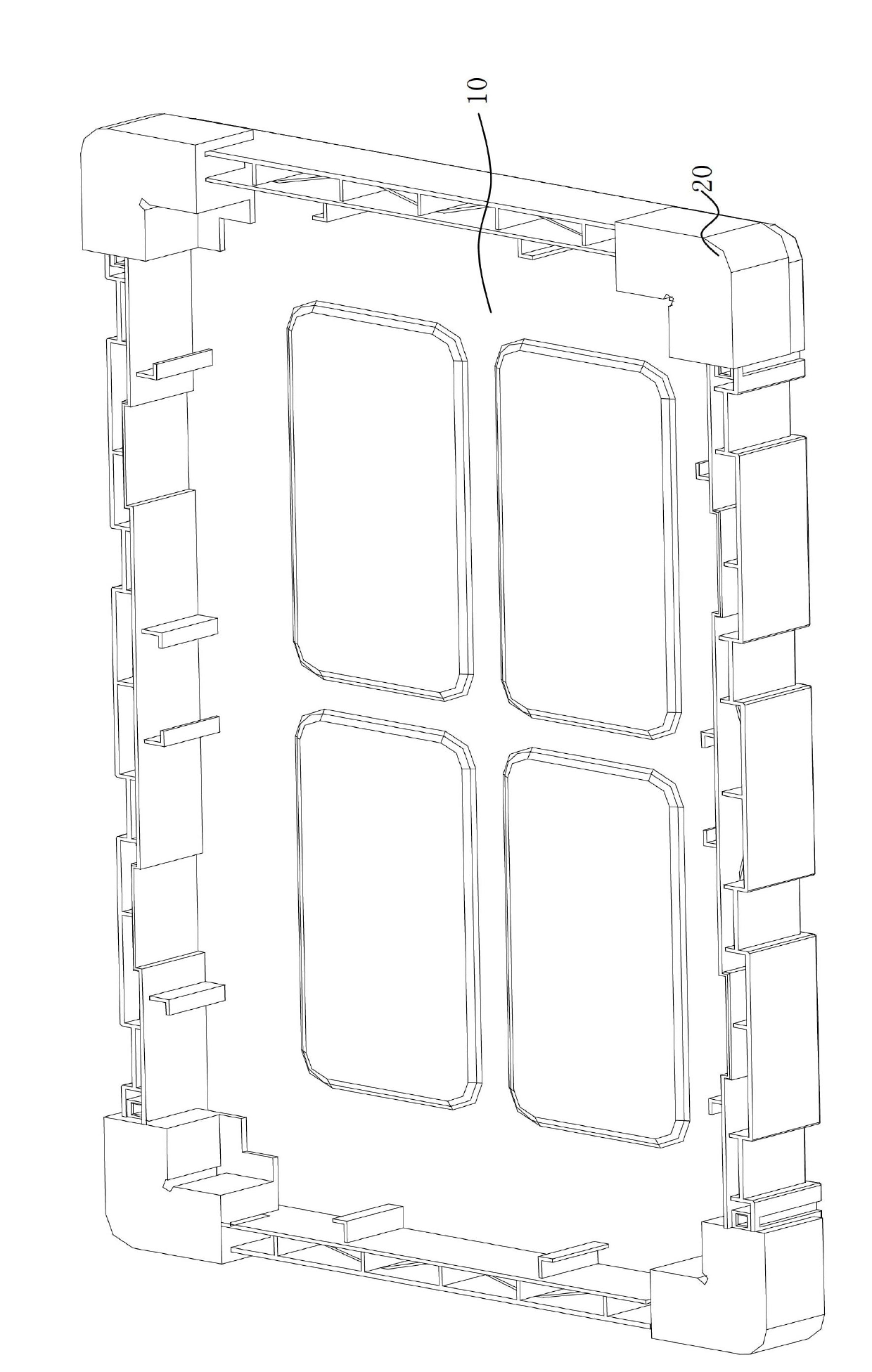
[0031] Please refer to figure 2 and image 3 , figure 2 It is a structural schematic diagram of a preferred embodiment of the buffer block structure of the present invention, image 3 It is a structural schematic diagram of a preferred embodiment of the packaging box of the present invention. The packaging box shown in the figure includes a box body 10...


PUM


Abstract

The invention relates to a buffer stop block structure and a corresponding package box body. The buffer stop block structure is arranged on a connecting corner of adjacent side surfaces of a main body of the corresponding box body, and the main body of the box body is used for placing a liquid crystal display panel. The buffer stop block structure comprises a fixing part, a connecting part and a box body buffer part. The buffer stop block structure and the corresponding box body have the advantages that the manufacture cost is low, the buffer fixing effect is good, and the technical problems that the manufacture cost of the existing package box is high, and the environment pollution is possibly caused are solved.

Description

technical field [0001] The invention relates to the technical field of packaging, in particular to a buffer block structure for packaging liquid crystal display panels and a corresponding packaging box. Background technique [0002] With the rapid progress and development of display technology, the traditional cathode ray tube (cathode ray tube, CRT) has been gradually eliminated due to problems such as poor space utilization and large energy consumption, and has been replaced by liquid crystal display (liquid crystal display, LCD). However, due to its thinness, fragility and other characteristics, liquid crystal displays have higher requirements for corresponding packaging boxes. [0003] The traditional packing box of liquid crystal display such as figure 1 as shown, figure 1 It is a structural schematic diagram of a packaging box in the prior art. The packaging box includes a box body, which is provided with a fixed structure matching the size and shape of the liquid c...

Claims


Application Information

Patent Timeline
IPC IPC(8): B65D81/113B65D85/38
CPCB65D81/05B65D85/48B65D81/113B65D81/056
Inventor 陈仕祥郭仪正程加河胡乾双
Owner TCL CHINA STAR OPTOELECTRONICS TECH CO LTD
Why Eureka
Try Eureka