Concrete piling process and drilling machine special for same

A technology of concrete and technology, which is applied in the direction of sheet pile wall, foundation structure engineering, construction, etc., can solve problems such as inability to drill holes, blockage of horizontal drilling holes, and difficulty in ensuring structural strength, so as to prevent pile holes from collapsing, increase service life, The effect of improving drilling efficiency

Inactive Publication Date: 2012-09-19
SHANDONG HONGTAI CONSTR GROUP
View PDF9 Cites 15 Cited by
  • Summary
  • Abstract
  • Description
  • Claims
  • Application Information

AI Technical Summary

Problems solved by technology

[0016] This structure satisfies the function of increasing the cross-sectional area of ​​the bottom of the pile body. Compared with the straight pile, it can make the pile body firmer, but there are some shortcomings due to structural reasons: 1. The oil cylinder is set in the steel pipe, so only cement or For the filling of other fluid slurry, if the concrete slurry is filled, the concrete is difficult to pass through, then after the filled concrete slurry enters the steel pipe, the oil cylinder cannot expand outward due to the existence of sand and gravel, and the oil cylinder is filling the concrete slurry. 2. When the drill bit is drilling down, mud and sand are easy to enter the steel pipe, blocking the whereabouts of the cement slurry and making it impossible to pour; 3. The drill bit for bottom expansion is two pieces Since it is only supported and driven by the working oil cylinder without other fixing measures, it is obvious that the strength of its structure can only be applied and constructed in soft soil environments, and it is difficult to use in hard soil or geological environments. If used, it is very easy to damage, and cannot guarantee the normal operation requirements of the construction
[0019] However, this process has some defects. 1. The expansion cutter is set at the position of the outer helical blade of the drill pipe. In this way, when drilling, because there is no protection measure for the expansion cutter, the expansion cutter is very easy to damage, especially in poor geological conditions. Next, 2. In addition, only the upper part of the working cylinder is used to pull the pull rod, which requires a higher working strength, because materials including soil, sand, etc. are filled in the pile holes formed by the spiral blades, how to ensure the pulling of the pull rod is a problem ;3. The way of setting the expansion knife in the slideway determines that the length of the expansion knife cannot be too long, that is to say, it is impossible or difficult to extend the length of the expansion knife beyond the distance between the pull rod and the outer diameter of the spiral blade, and the expansion knife It is also not easy to be too large in size, so the size of the expanded r...

Method used


Image

  • Concrete piling process and drilling machine special for same
  • Concrete piling process and drilling machine special for same
  • Concrete piling process and drilling machine special for same

Examples


Embodiment

[0088] Embodiment, a kind of concrete pile forming technology, this technology comprises the following steps:

[0089] A. Determine the pile position;

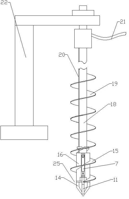
[0090] B. Move the long auger to the working position;

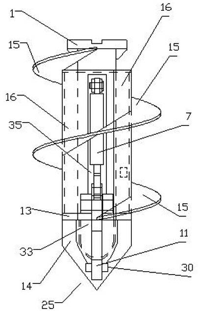
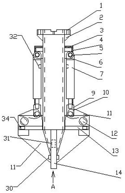
[0091] C. Vertical drilling: the bottom of the long helical drill rod is provided with a first drill bit for drilling in the vertical direction, and the long helical drill rod is provided with a position close to the first drill bit that can gradually open and close in the horizontal direction. The second drill bit on the first drill bit; when drilling, the second drill bit is closed on the first drill bit to form a combined drill bit for drilling down, and the pile hole is drilled to the required depth, and the down drilling is stopped;

[0092] D. Bottom reaming: In this step, the pile hole at the bottom is laterally reamed by gradually opening the second drill bit, until the second drill bit is fully opened, and the bottom reaming is completed to form a pile hole wit...

Embodiment 2

[0102] Embodiment 2, a kind of concrete pile forming technology, this technology comprises the following steps:

[0103] A. Determine the pile position through the GPS positioning module;

[0104] B. Move the long auger drill to the working position through the GPS positioning module;

[0105] C. Vertical drilling: the bottom of the long helical drill rod is provided with a first drill bit for drilling in the vertical direction, and the long helical drill rod is provided with a position close to the first drill bit that can gradually open and close in the horizontal direction. The second drill bit on the first drill bit; when drilling, the second drill bit is closed on the first drill bit to form a combined drill bit for downward drilling, and is positioned by the GPS positioning module, and the pile hole is drilled to the required depth, and the downward drilling is stopped ;

[0106] D. Bottom reaming: In this step, the pile hole at the bottom is horizontally reamed by gra...

Embodiment 3

[0117] Embodiment 3, a kind of concrete pile forming technology, this technology comprises the following operations:

[0118] A. Determine the pile position;

[0119] B. Move the long auger to the working position;

[0120] C. Vertical drilling: the bottom of the long helical drill rod is provided with a first drill bit for drilling in the vertical direction, and the long helical drill rod is provided with a position close to the first drill bit that can gradually open and close in the horizontal direction. The second drill bit on the first drill bit; when drilling, the second drill bit is closed on the first drill bit to form a combined drill bit for drilling down, and the drill pipe hole of the long spiral drill rod is closed; the pile hole is drilled to the required depth, stop drill down;

[0121] D. Bottom reaming: In this step, the pile hole at the bottom is laterally reamed by gradually opening the second drill bit, until the second drill bit is fully opened, and the ...


PUM


Abstract

The invention discloses a concrete piling process and a drilling machine special for the same. The concrete piling process is applicable to filled concrete and fluid such as cement, and can meet construction requirements of complicated geological conditions comprising high hardness or high collapsibility; by the concrete piling process, drilling, filling and broaching are completed at a time, and diameter-varied piles with high quality requirements can be molded; and transverse drilling can be realized at any position of pile holes accurately; the concrete piling process is convenient to construct and high in reliability; and the drilling machine special for the concrete piling process can meet requirements of a construction process, effectively shorten construction periods and accurately position the pile holes and determine the depths of the pile holes, and is reasonable in structure, high in strength and long in service life.

Description

technical field [0001] The invention relates to a pile-forming process and special equipment, in particular to a concrete pile-forming process and a special drilling rig. Background technique [0002] The existing cast-in-place piles include vibrating sinking pipe cast-in-place piles, mud wall retaining cast-in-place piles, and auger-drilled sandless concrete cast-in-place piles. [0003] The construction technology of vibrating sinking pipe grouting pile is as follows: 1. Start the vibrating hammer to sink the pile pipe to the design depth; 2. Lower the reinforcement cage to the design elevation in the pile pipe; 3. Putting concrete into the pile pipe; 4. Extubation into a pile. The disadvantage is that when the ground soil layer contains a thicker sand layer, the vibrating immersed tube cannot pass through the sand layer; and the vibratory hammer has a large power and is located on the top of the pile pipe, so there is a lot of noise during construction, and constructi...

Claims


Application Information

Patent Timeline
IPC IPC(8): E02D5/48E02D5/36E02D15/04
Inventor 常炳岭王增金吴俊喜王亦德
Owner SHANDONG HONGTAI CONSTR GROUP
Why Eureka
Try Eureka