LED (light-emitting diode) dot matrix display screen and combined dot matrix display screen

A display screen and LED chip technology, applied in the field of display screens, can solve problems such as poor heat conduction effect, high temperature of LED chips and other devices, shortened service life, etc., and achieve good heat dissipation effect, good waterproof effect, and simple structure.

Inactive Publication Date: 2012-09-19
东莞市万兴智能科技有限公司
View PDF10 Cites 12 Cited by
  • Summary
  • Abstract
  • Description
  • Claims
  • Application Information

AI Technical Summary

Problems solved by technology

For the LED chip integrated package light source, because the chip is relatively concentrated, the heat in the light source area is high, which can easily lead to excessive temperature of the LED chip and other devices.
If a large amount of heat cannot be dissipated in time, it will cause a series of problems: for example, it will accelerate the aging of LED chips and other devices, shorten the service life, and even cause the LED chips to burn out; it will cause the wavelength of blue LEDs to red shift and affect the color of white LEDs. If the wavelength shifts too much and deviates from the absorption peak of the phosphor, it will lead to a decrease in the quantum efficiency of the phosphor and affect the light output efficiency; the temperature also has a great impact on the radiation characteristics of the phosphor. , the quantum efficiency of phosphor powder decreases, and the radiation wavelength will also change. The change of phosphor powder radiation wavelength will also cause changes in the color temperature and chromaticity of white LEDs. Higher temperatures will also accelerate the aging of phosphor powder.
The display module is directly mounted or welded with single-color or double-color or three-color LED chips in the matrix dots of the printed circuit board, and is filled with metal copper or other Heat conduction material conducts heat, the heat conduction effect is poor, and the process is complicated
This utility model also does not disclose how to seal the printed circuit board

Method used


Image

  • LED (light-emitting diode) dot matrix display screen and combined dot matrix display screen
  • LED (light-emitting diode) dot matrix display screen and combined dot matrix display screen
  • LED (light-emitting diode) dot matrix display screen and combined dot matrix display screen

Examples


Embodiment 1

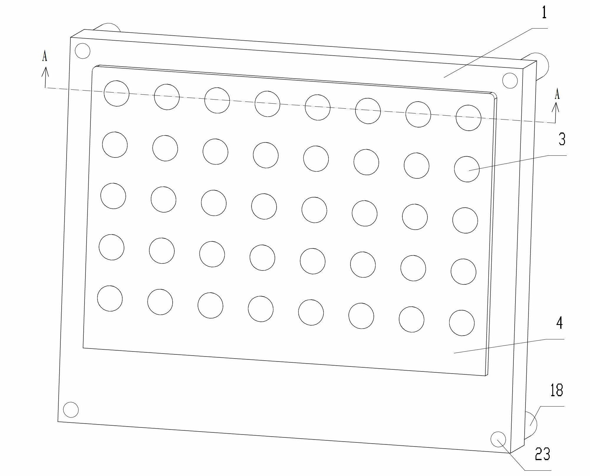
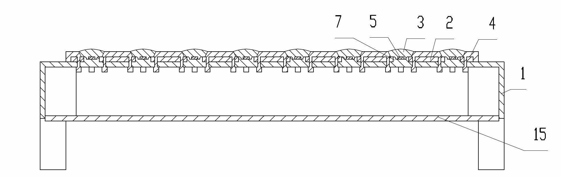
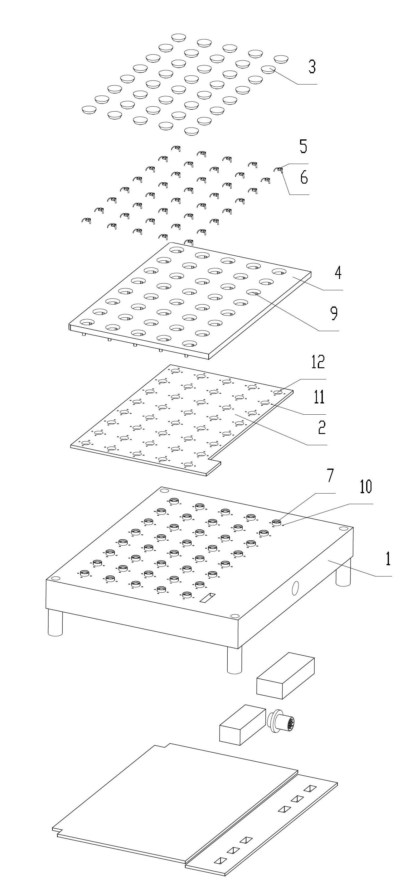
[0049] Such as Figure 1 to Figure 4 As shown, an LED dot matrix display screen includes a heat dissipation base 1, a PCB board 2, a light-transmitting encapsulation colloid 3 for packaging LED chips, a plastic plate 4 for forming and encapsulating the light-transmitting encapsulation colloid 3 for LED chips, and a uniform array of single primary colors LED light-emitting unit, imaging controller, layout circuit conductive layer (not shown); the layout circuit conductive layer is directly arranged on the PCB board 2, and the imaging controller is directly arranged on the back 2 of the PCB board away from the layout circuit conductive layer. face.

[0050] The LED light-emitting unit includes a single-color LED chip 5, a gold wire 6 electrically connected to the LED chip 5 and the conductive layer of the layout circuit, and a light-transmitting encapsulant 3 for encapsulating the LED chip 5; each LED chip 5 is passed through the layout. The conductive layer of the circuit is s...

Embodiment 2

[0053] Such as Figure 5 to Figure 8 As shown, an LED dot-matrix display screen is different from Embodiment 1 in that a third heat dissipation through hole 52 penetrating through the plastic plate 51 is provided at the center of each of the four adjacent chip fixing bosses 50, penetrating through the The second heat dissipation through hole 54 of the PCB board 53, the first heat dissipation through hole 56 penetrating through the heat dissipation base 55, and the fourth heat dissipation through hole 58 penetrating through the runner cover plate 57, each chip fixing boss 50 is connected with the first heat dissipation through hole Holes 56 are adjacent. The imaging controller is directly arranged on the surface of the PCB 2 away from the conductive layer of the layout circuit. The uniform array of LED light emitting units has dual primary colors.

[0054] An outer wall 59 of the airtight chamber extends on the surface of the heat dissipation base 55 facing the PCB 53 , and a...

Embodiment 3

[0058] Such as Figure 9 As shown, the difference from Embodiment 2 is that a lateral heat dissipation fin 82 and a vertical heat dissipation fin 83 are provided on the side of the heat dissipation base 80 away from the PCB board 81 . The heat dissipation fins 82 are parallel to each other, and the heat dissipation fins 83 are parallel to each other. The gaps between the heat dissipation fins 82 and the heat dissipation fins 83 , the first heat dissipation through hole 84 , the second heat dissipation through hole 86 , and the third heat dissipation through hole 85 connected in series form a convective gas heat dissipation channel. The first heat dissipation through hole 84 runs through the heat dissipation fin 82 and the heat dissipation fin 83 , and the adjacent heat dissipation fins are not connected. The end of the first heat dissipation through hole 84 facing away from the PCB board 81 communicates with the outside air through the gap between the heat dissipation fins 82...


PUM


Abstract

The invention discloses an LED (light-emitting diode) dot matrix display screen and a combined dot matrix display screen. The dot matrix display screen comprises a heat-dissipating substrate, a PCB (printed circuit board), an uniformly-arrayed LED light-emitting unit, an imaging controller, a layout circuit conducting layer, a pervious-to-light packaging colloid for packaging LED chips, and a plastic plate forming the pervious-to-light packaging colloid for packaging the LED chips, wherein the LED light-emitting unit comprises more than one LED chips, guide lines and the pervious-to-light packaging colloid; the guide lines electrically connect the LED chips with the layout circuit conducting layer, and the pervious-to-light packaging colloid is used for packaging the LED chips; a hermetically-sealed outer cavity side wall which is hermetically connected with the plastic plate and the heat-dissipating substrate is arranged between the plastic plate and the heat-dissipating substrate; the heat-dissipating substrate, the hermetically sealed outer cavity side wall and the plastic plate defines a hermetically-sealed cavity, and the PCB is accommodated in the hermetically-sealed cavity; and the heat-dissipating substrate, the plastic plate and the pervious-to-light packaging colloid are directly contacted with the outside air. The dot matrix display screen disclosed by the invention has the advantages that of being simple in structure and low in cost and having good waterproof and heat-dissipating effects since the PCB is accommodated in the hermetically-sealed cavity formed by the heat-dissipating substrate, the hermetically sealed outer cavity side wall and the plastic plate.

Description

technical field [0001] The invention relates to a display screen, in particular to an LED dot matrix display screen and a combined dot matrix display screen. Background technique [0002] Compared with traditional light sources, LED light-emitting diodes have no lead, mercury, no flicker, energy saving and environmental protection, long service life, fast response speed, vibration resistance, easy maintenance, high brightness, low energy consumption, less ultraviolet radiation and environmental pollution, and use High security and many other advantages are widely used in display screen imaging. [0003] The light decay and lifetime of LED light sources are directly related to their junction temperature. LED lights, especially high-power LED light sources, concentrate heat when emitting light. If the heat generated by the LED chip is not dissipated in time, the junction temperature will be very high and the lifespan will be short. According to Ares' law, for every 10°C decr...

Claims


Application Information

Patent Timeline
Patent Type & Authority Applications(China)
IPC IPC(8): G09F9/33H05K7/20
CPCG09F9/33H01L33/64H01L33/48
Inventor 杨东佐
Owner 东莞市万兴智能科技有限公司
Why Eureka
Try Eureka