Electro-wetting display

An electrowetting display, the first fluid technology, applied in the direction of static indicators, instruments, optics, etc., can solve the problem that the color display effect cannot be achieved

Active Publication Date: 2014-06-18
BOE TECH GRP CO LTD
View PDF13 Cites 0 Cited by
  • Summary
  • Abstract
  • Description
  • Claims
  • Application Information

AI Technical Summary

Problems solved by technology

[0007] Although electrowetting display technology has many advantages, it has not yet achieved a satisfactory color display effect.

Method used


Image

  • Electro-wetting display
  • Electro-wetting display
  • Electro-wetting display

Examples


Embodiment Construction

[0044] The invention provides an electrowetting display, so that each pixel can display more than two colors, so as to achieve the purpose of electrowetting display full color. The present invention will be further described through specific embodiments below in conjunction with the accompanying drawings.

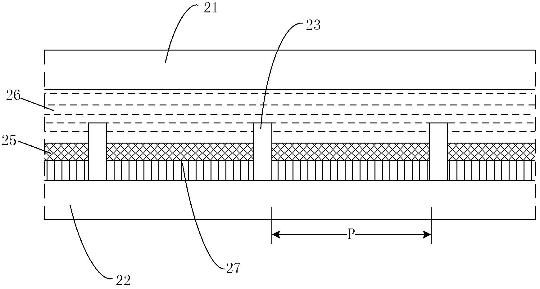
[0045] First, please refer to figure 2 , the electrowetting display described in the embodiment of the present invention includes:

[0046] A first substrate 21 , a second substrate 22 disposed below the first substrate 21 , a plurality of isolation walls 23 , a first fluid 25 and a second fluid 26 . Wherein, the plurality of partition walls 23 are arranged on the second substrate 22 in a lattice shape, thereby defining a plurality of pixel units P; the first fluid 25 is filled in the lattice-like space formed by adjacent partition walls 23 , and the first fluid 25 is immiscible with the second fluid 26, the second fluid 26 is transparent and has conductivity or polarity...


PUM


Abstract

An embodiment of the disclosed technology discloses an electrowetting display, comprising a first substrate, a second substrate disposed opposite to and under the first substrate, a plurality of separation walls, a first fluid, and a second fluid, wherein the plurality of separation walls are disposed in grid on the second substrate to define a plurality of pixel units, and the first fluid is filled in the spaces of the grid formed by adjacent separation walls, the first fluid is opaque and does not mix with the second fluid, the second fluid is transparent, has conductivity or polarity, and is filled between the first fluid and the first substrate; and wherein a colored layer is disposed for each pixel unit, and the colored layer has at least one predetermined color and is between the first fluid and the second substrate.

Description

technical field [0001] The invention relates to the technical field of electrowetting display, in particular to an electrowetting display. Background technique [0002] The principle of electrowetting (Electrowetting) display technology is to use the phenomenon of electrowetting or electrocapillary (Electrocapillary) to change the surface free energy (Free Surface Energy) of the fluid by controlling the fluid to be subjected to an electric field, so that the distribution area of ​​the fluid changes. And then control the change of the pixel to realize the specific display effect. Electrowetting display technology has attracted much attention due to its characteristics of low power consumption, wide viewing angle and high response speed. [0003] Please refer to Figure 1A-1B , is a schematic diagram of a typical electrowetting display pixel in the prior art. in Figure 1A When no operating voltage is applied, the colored first fluid forms a flat film layer 12 between the t...

Claims


Application Information

Patent Timeline
Patent Type & Authority Patents(China)
IPC IPC(8): G02B26/02G09G3/34
CPCG09G2300/0452G09G2300/0426G02B26/005G09G3/348G09G3/2003
Inventor 田肖雄薛建设赵吉生
Owner BOE TECH GRP CO LTD
Why Eureka
Try Eureka