Hydraulic password door

A coded door and hydraulic technology, which is applied in the direction of coded locks, door leaves, door/window accessories, etc., can solve the problems of easy aging of rubber sealing elements, the door is not suitable for hydraulic code system, and poor reliability, so as to increase the reliability of use Effects related to maintainability, reduced work efficiency, and easy wear

Inactive Publication Date: 2012-11-21
周跃平
View PDF0 Cites 4 Cited by
  • Summary
  • Abstract
  • Description
  • Claims
  • Application Information

AI Technical Summary

Problems solved by technology

[0002] Generally, multiple mechanisms such as the password mechanism, the lock mechanism, and the alarm mechanism of the password door are concentrated in the same working chamber. Such a door is not suitable for the hydraulic password system; It is best not to use rubber hydraulic sealing components for each component of the password system, because rubber sealing components are prone to aging and failure, many failures, poor reliability, and even the best password system will bring a lot of trouble to users. On the hydraulic password door, there is no rubber hydraulic sealing element, and a series of problems have never been encountered in the existing hydraulic control technology. The hydraulic password system is prone to leakage of working fluid. The leakage is divided into internal leakage and external leakage. It leaks out of the door through various holes on the door, such as lock bolt holes, oil pump handle holes, etc. The larger the working chamber on the door, the more mechanisms there are, and the more ways of leakage. The working fluid leaks into various parts of the working chamber and When stored, the oil in the fuel tank is getting less and less, and the oil pump may not be able to absorb the working fluid; these are the problems encountered in the actual development work

Method used


Image

  • Hydraulic password door
  • Hydraulic password door
  • Hydraulic password door

Examples


Embodiment Construction

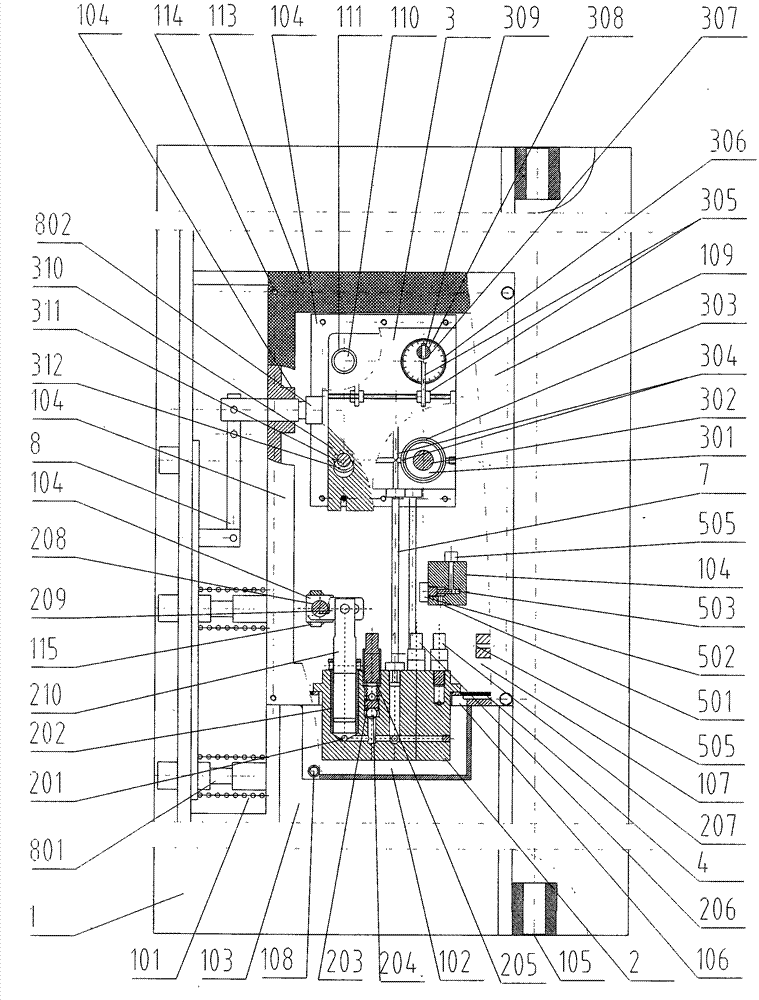
[0052] Attached figure 1 What is shown is one of the embodiments of the present invention, and at the same time, it integrates a variety of optimized structures that we have summarized in the development process over the past few years.

[0053] The door panel 1 has a password working chamber 107; the inner wall of the password working chamber 107 is painted with oil-resistant anti-rust paint (not marked in the figure) to prevent rust; the weather-resistant strip 113 is installed between the door panel 1 and the inner sealing plate 109, which is effective Prevent the working fluid from leaking out between the door panel 1 and the inner sealing plate 109; the filter device 4 is installed on the oil return passage 106 between the password working chamber 107 and the fuel tank 102, and the filter device 4 effectively prevents impurities in the password working chamber 107 from entering Fuel tank 102; the filling hole 503 communicates with the outside of the door panel 1, the filling ...


PUM


Abstract

The invention relates to a hydraulic password door in the field of password safety. The hydraulic password door comprises a door plate, and is characterized in that the door plate is provided with a password working chamber which comprises an oil tank and a password wheel hole, wherein the oil tank is at the bottom of the password working chamber. The password working chamber is separated from other working chambers on the door, and therefore, the contact space of working liquid is reduced, the way of the working liquid leakage is reduced, the processing cost is lowered, and the using reliability is improved effectively. The oil tank is at the bottom of the password working chamber, a hydraulic password system is assembled in the password working chamber and inner leakage of the hydraulic password system returns to the oil tank automatically, and therefore, the working liquid cannot be deposited out of the oil tank or on other parts of the chamber heavily. According to the hydraulic password door provided by the invention, the working liquid can be prevented from leakage effectively, and the using reliability of the hydraulic password system is improved. The hydraulic password door has the advantages of novelty, practicality and higher creativity.

Description

Technical field [0001] The invention relates to configuring a hydraulic password door for hydraulic password security equipment including safes, anti-theft doors and the like. Background technique [0002] The password mechanism, lock bolt mechanism, alarm mechanism and other mechanisms of general password doors are concentrated in the same working chamber. Such doors are not suitable for hydraulic password systems. In addition, according to our years of development and testing of hydraulic password system products, hydraulic It is best not to use rubber hydraulic sealing components for each component of the password system, because the rubber sealing components are prone to aging and cause failures, many failures, and poor use reliability. No matter how good the password system, it will also bring a lot of trouble to users. The hydraulic password system is centralized. On the hydraulic code door, there is no rubber hydraulic sealing element, and it has encountered a series of pr...

Claims


Application Information

Patent Timeline
Patent Type & Authority Applications(China)
IPC IPC(8): E06B3/70E05B51/02E05B37/20E05B3/00E05B63/14
Inventor 周跃平周星果周文珺尹雄鹰周向阳
Owner 周跃平
Why Eureka
Try Eureka