A waste heat recovery device for cement production in the construction field

A waste heat recovery device and technology in the field, applied in the field of construction and machinery, can solve the problems of low energy utilization rate, low heat absorption efficiency, and increased water heat absorption cost, etc., to achieve enhanced heat absorption effect, improve heat absorption efficiency, The effect of preventing local high temperature

Active Publication Date: 2021-12-14
中林国际建设有限公司
View PDF0 Cites 0 Cited by
  • Summary
  • Abstract
  • Description
  • Claims
  • Application Information

AI Technical Summary

Problems solved by technology

[0002] As a common building material, cement has been widely used, but the production process of cement will generate a lot of waste heat. If the waste heat is not recycled, it will cause waste of energy, resulting in low energy utilization rate and not meeting the requirements of the current green environment. economic needs
The existing waste heat recovery device mainly absorbs heat into the water for storage or post-processing through water heat absorption, but this method has low heat absorption efficiency, and the waste heat recovery effect is not ideal, and the water flows after not completely absorbing the heat. away, leading to low utilization of water resources and increasing the cost of water heat absorption

Method used


Image

  • A waste heat recovery device for cement production in the construction field
  • A waste heat recovery device for cement production in the construction field
  • A waste heat recovery device for cement production in the construction field

Examples


Embodiment Construction

[0016] The waste heat recovery device for cement production in the construction field of the present invention will be clearly and completely described below in conjunction with the accompanying drawings.

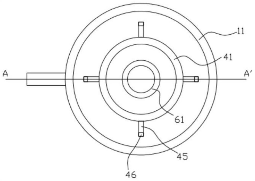
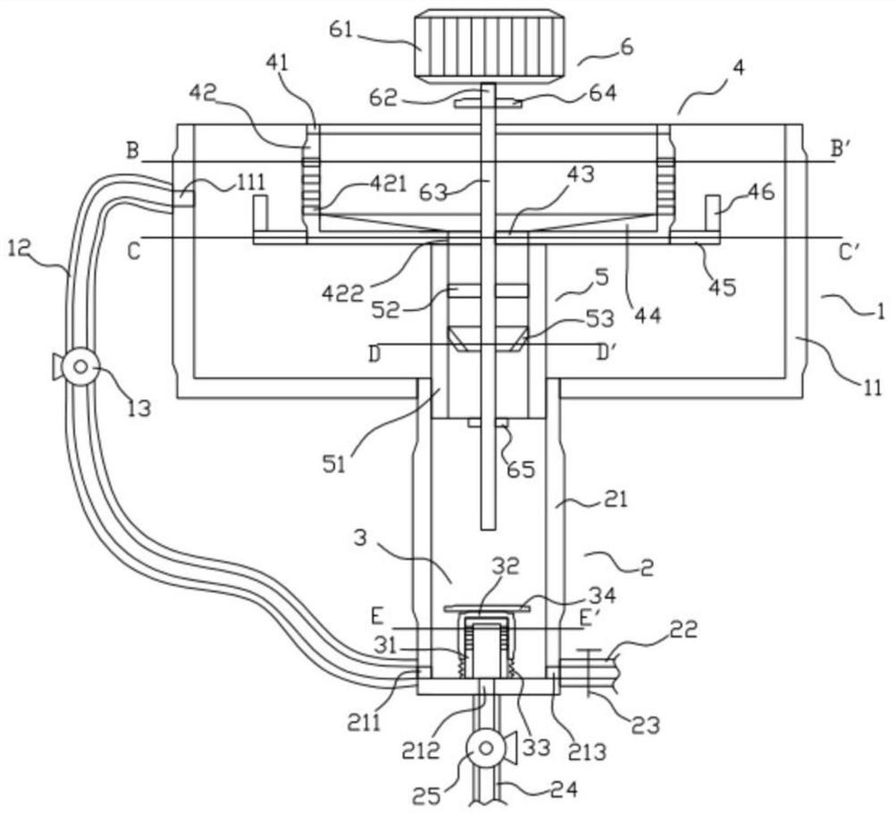
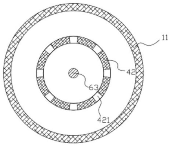
[0017] Such as Figure 1 to Figure 6 As shown, the waste heat recovery device for cement production in the construction field of the present invention includes an upper shell structure 1, a lower shell structure 2 arranged below the upper shell structure 1, a closed structure 3 arranged in the lower shell structure 2, and a The rotating structure 4 in the upper shell structure 1 , the heat exchange structure 5 arranged below the rotating structure 4 , and the driving structure 6 located above the closed structure 3 .

[0018] Such as Figure 1 to Figure 4 As shown, the upper casing structure 1 includes an upper casing 11 , a connecting pipe 12 arranged outside the upper casing 11 , and a water pump 13 arranged on the connecting pipe 12 . The upper end of the upper shell 1...


PUM


Abstract

A waste heat recovery device for cement production in the construction field, comprising an upper shell structure, a lower shell structure arranged under the upper shell structure, a rotating structure arranged in the upper shell structure, a heat exchange structure arranged under the rotating structure, and an upper shell structure It includes an upper case, a connecting pipe arranged on the upper case, and a water pump arranged on the connecting pipe. The side of the upper case is provided with a first through hole, and the upper end of the connecting pipe is aligned with the first through hole and fixed to the side of the upper case. connection, the lower shell structure includes the lower shell, the upper end of the lower shell penetrates the inner and outer surfaces of the upper shell and is fixedly connected with it, the side of the lower shell is provided with a second through hole, the lower end of the connecting pipe is aligned with the second through hole and connected with the lower shell Side fixed connection. In the present invention, by setting the floating frame and the rotating frame, the floating frame can float on the water surface, and the rotating frame is immersed in the water, so that the water in the upper shell can continuously enter the rotating frame through the sixth through hole on the rotating frame , so that water can fully contact and absorb hot air.

Description

technical field [0001] The invention relates to the field of mechanical technology, in particular to a waste heat recovery device for cement production in the construction field. Background technique [0002] As a common building material, cement has been widely used, but the production process of cement will generate a lot of waste heat. If the waste heat is not recycled, it will cause waste of energy, resulting in low energy utilization rate and not meeting the requirements of the current green environment. economic needs. The existing waste heat recovery device mainly absorbs heat into the water for storage or post-processing through water heat absorption, but this method has low heat absorption efficiency, and the waste heat recovery effect is not ideal, and the water flows after not completely absorbing the heat. Going away leads to low utilization of water resources and increases the cost of water heat absorption. [0003] Therefore, it is necessary to provide a new ...

Claims


Application Information

Patent Timeline
Patent Type & Authority Patents(China)
IPC IPC(8): F28D21/00B01F7/18B01D33/15B01D33/42
CPCF28D21/001B01D33/15B01D33/42B01F27/90Y02P70/10
Inventor 廖晓敏
Owner 中林国际建设有限公司
Why Eureka
Try Eureka