F-theta lens and optical system

An optical system and lens technology, applied in the field of optical lenses, can solve the problems of limited scanning range of the lens and difficult aberration correction, and achieve the effect of improving the scannable range, small focusing spot, and expanding the application range.

Active Publication Date: 2012-12-05
HANS LASER TECH IND GRP CO LTD
View PDF5 Cites 4 Cited by
  • Summary
  • Abstract
  • Description
  • Claims
  • Application Information

AI Technical Summary

Problems solved by technology

However, the larger the field of view and the larger the scanning range, the more difficult it is to correct aberrations
However, the scanning range of lenses currently on the market is limited. There is no F-theta lens with a scanning range exceeding 600mm×600mm, especially there is no CO2 F-theta lens with a scanning range exceeding 600mm×600mm.

Method used


Image

  • F-theta lens and optical system
  • F-theta lens and optical system
  • F-theta lens and optical system

Examples


Embodiment 1

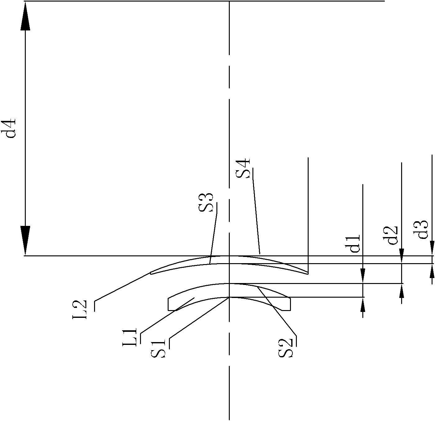
[0014] Example 1, as figure 2 As shown, the present invention provides a two-piece F-theta lens, which includes a first lens L1 and a second lens L2 arranged in sequence along the direction of incident light, and the first lens L1 is a meniscus negative lens , the second lens L2 is a meniscus positive lens, the curved surfaces of the two lenses are curved toward the incident direction of the light; the field angle of the lens is 2ω=70°, the light entrance aperture is 30mm, and its scanning range is 608mm×608mm.

[0015] In this embodiment, the focal length of each lens and the system focal length of the F-theta lens respectively satisfy:

[0016] -1.2

[0017] 0.5

[0018] Wherein, f1 is the focal length of the first lens, f2 is the focal length of the second lens, and f is the system focal length of the F-theta lens.

[0019] Preferably, the focal length of each lens and the system focal length of the F-theta lens further satisfy: f1 / f=-1.168; f2 / f=0.597....

Embodiment 2

[0022] Embodiment 2, under the condition that the above conditions are met, the present invention further provides an embodiment.

[0023] like figure 2 As shown, the first lens L1 includes two curved surfaces S1 and S2 with radii of curvature R1 and R2 respectively, and their central thickness is d1, where R1=-108.029mm, R2=-128.433mm, and d1=13.288mm; the second The lens L2 includes two curved surfaces S3 and S4 with radii of curvature R3 and R4 respectively, and the central thickness thereof is d3, where R3=-277.299mm, R4=-188.451mm, and d3=7.441mm; the second lens L2 and the imaging surface The distance on the optical axis is d4, and d4 is 743.3mm. The distance between the first lens L1 and the second lens L2 on the optical axis is d2, and d2 is 19.271 mm.

[0024] Further, both the first lens L1 and the second lens L2 are made of ZnSe.

[0025] The above specific structural parameters are as follows:

[0026]

[0027] Note: Negative numbers mean that the center of...

Embodiment 3

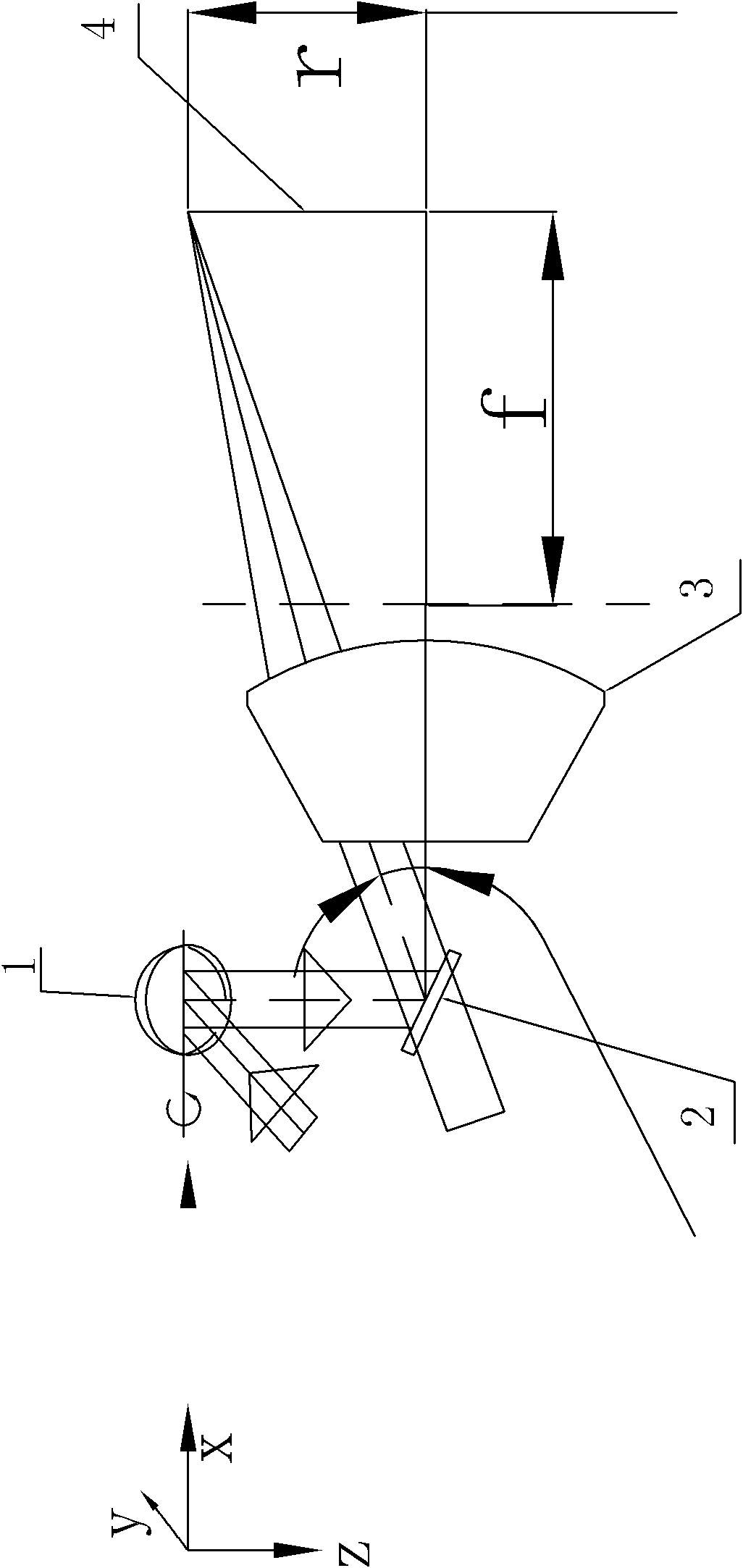
[0028] Embodiment 3, on the basis of Embodiment 1 or Embodiment 2, provides an optical system, such as figure 1 , 2 As shown, it includes a galvanometer system that can be rotated around the X-axis and the Y-axis and guides the light beam to scan at the F-theta lens 3, wherein the galvanometer system includes a first galvanometer 1 and a second galvanometer 2, and the F-theta lens 3. It includes a first lens L1 and a second lens L2 arranged in sequence along the light propagation direction, the first lens L1 is a meniscus negative lens, the second lens L2 is a meniscus positive lens, and the curved surfaces are all facing the light incident direction Curved; the field of view of the lens is 2ω=70°, the light entrance aperture is 30mm, and its scanning range is 608mm×608mm.

[0029] The focal lengths of the first and second lenses respectively satisfy the system focal length of the F-theta lens:

[0030] -1.2

[0031] 0.5

[0032] Wherein, f1 is the focal l...


PUM


Abstract

The invention provides an F-theta lens and an optical system. The F-theta lens comprises a first lens and a second lens, which are arranged in a light propagation direction in sequence; the first lens is a crescent-shaped negative lens; the second lens is a crescent-shaped positive lens; and curved surfaces of the first lens and the second lens are both bent toward a light incident direction; the incident light wavelength of the lens is 10.6 microns, view field angle 2 omega of the lens is 70 degrees, light incident aperture of the lens is 30 mm, and the scanning range of the lens is 608 mm X 608 mm. The F-theta lens provided by the invention is a large-range field flattening lens, which is designed through double-plate type negative-positive focal power distribution; and on the premise that energy concentration and small focusing spots of a laser are guaranteed, a scannable range can be further enlarged, so that the F-theta lens provided by the invention is beneficial for enlarging the application range of the laser machining industry.

Description

【Technical field】 [0001] The present invention relates to an optical lens, in particular to a wide-range F-theta lens and an optical system using the optical lens. 【Background technique】 [0002] At present, laser applications have penetrated into all aspects of our modern life, and various application optical systems in order to meet various process requirements are inseparable from laser applications. In the current market, the laser marking machine has gradually replaced various printing machines, screen printing machines, etc. with its fast speed, strong flexibility, no consumables, and permanent marking. [0003] The F-theta lens is a photographic objective with a large field of view, medium and small apertures, and medium and long focal lengths. The laser galvanometer marking machine is realized because of the F-theta lens. figure 1 It is a typical F-Theta mirror optical system. The light beam passes through two galvanometers 1 and 2 that rotate around the X-axis and...

Claims


Application Information

Patent Timeline
Patent Type & Authority Applications(China)
IPC IPC(8): G02B13/18G02B13/14
Inventor 汪玉树高云峰
Owner HANS LASER TECH IND GRP CO LTD
Why Eureka
Try Eureka