F-theta lens and optical system
An optical system and lens technology, applied in the field of optical lenses, can solve the problems of difficult aberration correction and limited scanning range of the lens, and achieve the effect of small focusing spot, improving the scanning range and expanding the application range.
- Summary
- Abstract
- Description
- Claims
- Application Information
AI Technical Summary
Problems solved by technology
Method used
Image
Examples
Embodiment 1
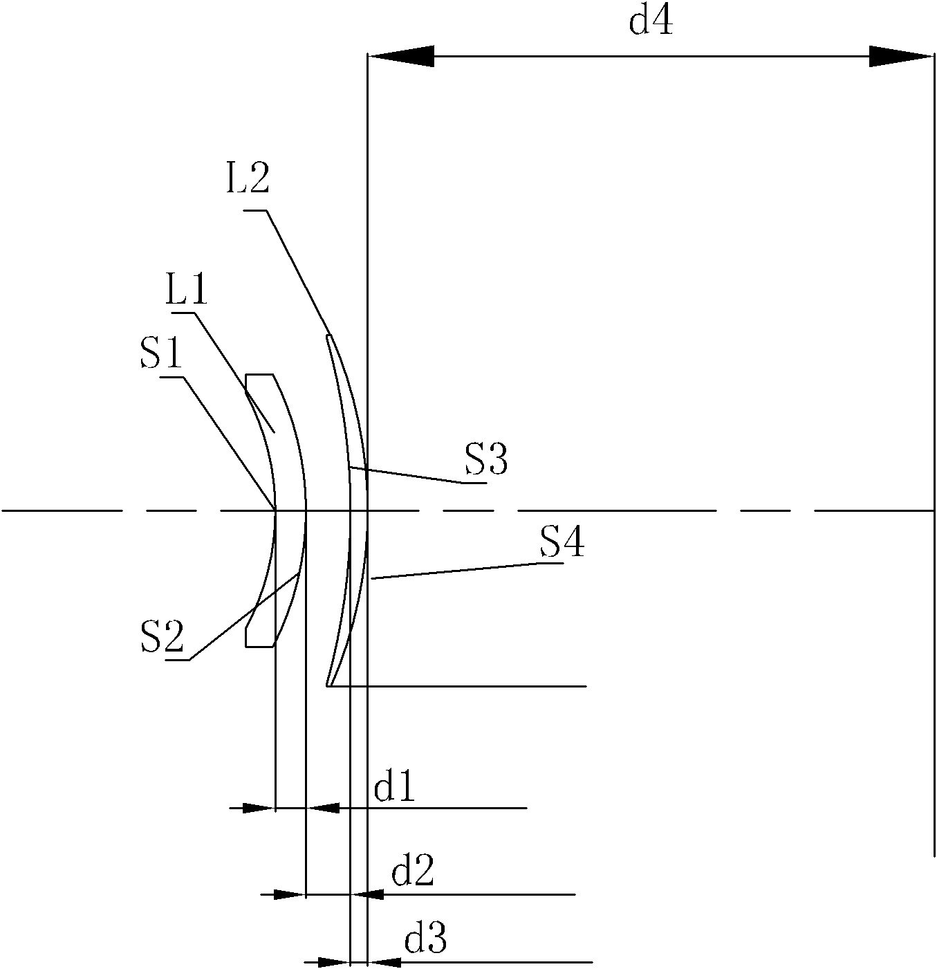
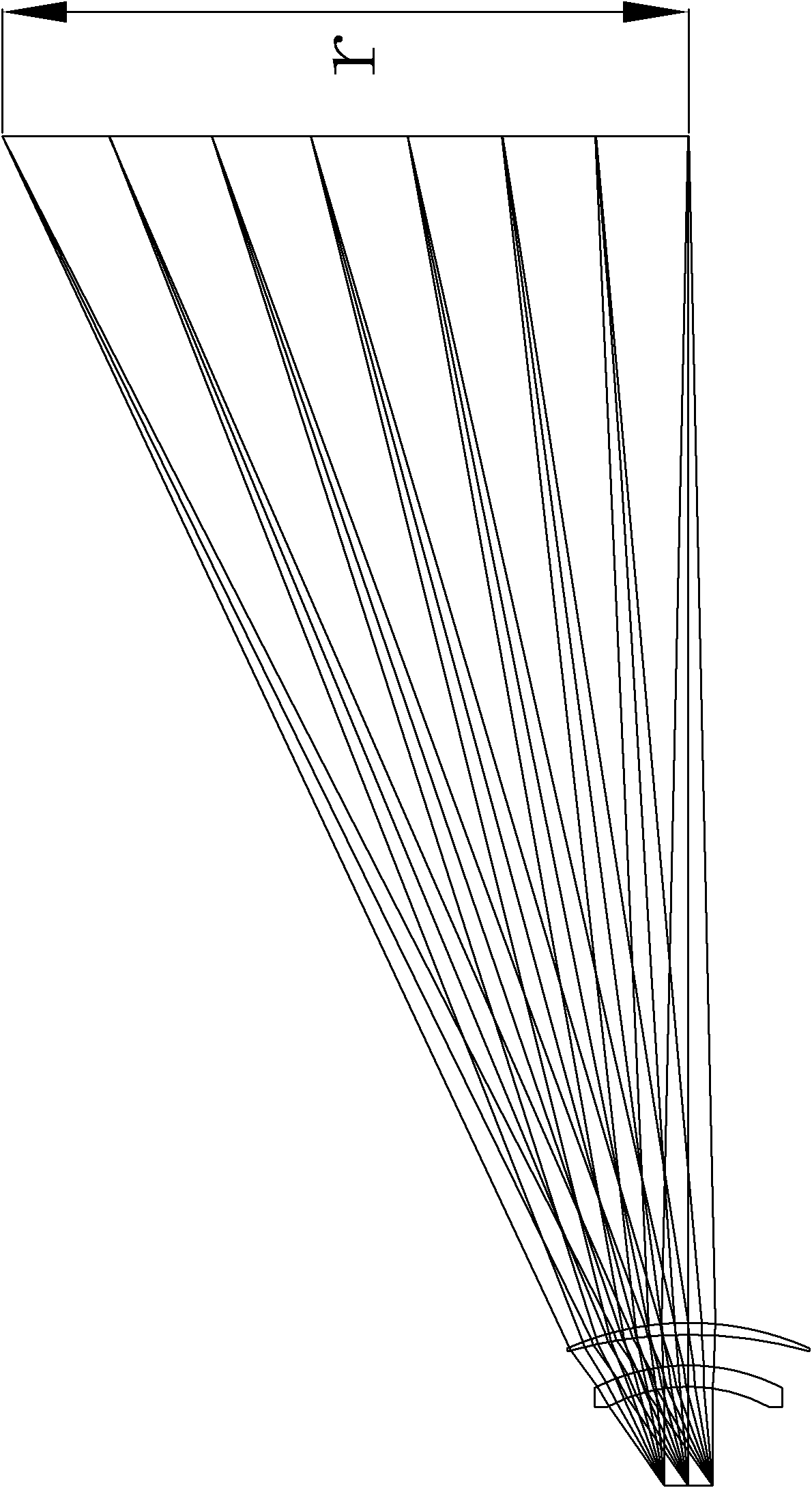
[0014] Example 1, such as figure 2 As shown, the present invention provides a double-piece F-theta lens, which includes a first lens L1 and a second lens L2 arranged in sequence along the light incident direction, and the first lens L1 is a meniscus negative lens , the second lens L2 is a positive meniscus lens, and the curved surfaces of the two lenses are all curved toward the light incident direction; the field angle of the lens is 2ω=70°, the light entrance aperture is 30mm, and the scanning range is 608mm×608mm.
[0015] In the present embodiment, the focal length of each lens and the system focal length of the F-theta lens satisfy:
[0016] -1.2
[0017] 0.5
[0018] Wherein, f1 is the focal length of the first lens, f2 is the focal length of the second lens, and f is the system focal length of the F-theta lens.
[0019] Preferably, the focal length of each lens and the system focal length of the F-theta lens further satisfy: f1 / f=-1.168; f2 / f=0.597....
Embodiment 2
[0022] Embodiment 2, on the condition that the above conditions are met, the present invention further provides an embodiment.
[0023] Such as figure 2 As shown, the first lens L1 includes two curved surfaces S1, S2 with curvature radii R1, R2 respectively, and its central thickness is d1, wherein, R1=-108.029mm, R2=-128.433mm, d1=13.288mm; the second Lens L2 includes two curved surfaces S3 and S4 with curvature radii R3 and R4 respectively, and its central thickness is d3, wherein R3=-277.299mm, R4=-188.451mm, d3=7.441mm; the second lens L2 and the imaging surface The distance on the optical axis is d4, and d4 is 743.3 mm. Wherein, the distance between the first lens L1 and the second lens L2 on the optical axis is d2, and d2 is 19.271 mm.
[0024] Further, both the first lens L1 and the second lens L2 are made of ZnSe.
[0025] The above specific structural parameters are as follows:
[0026]
[0027] Note: Negative numbers mean that the center of the surface is on ...
Embodiment 3
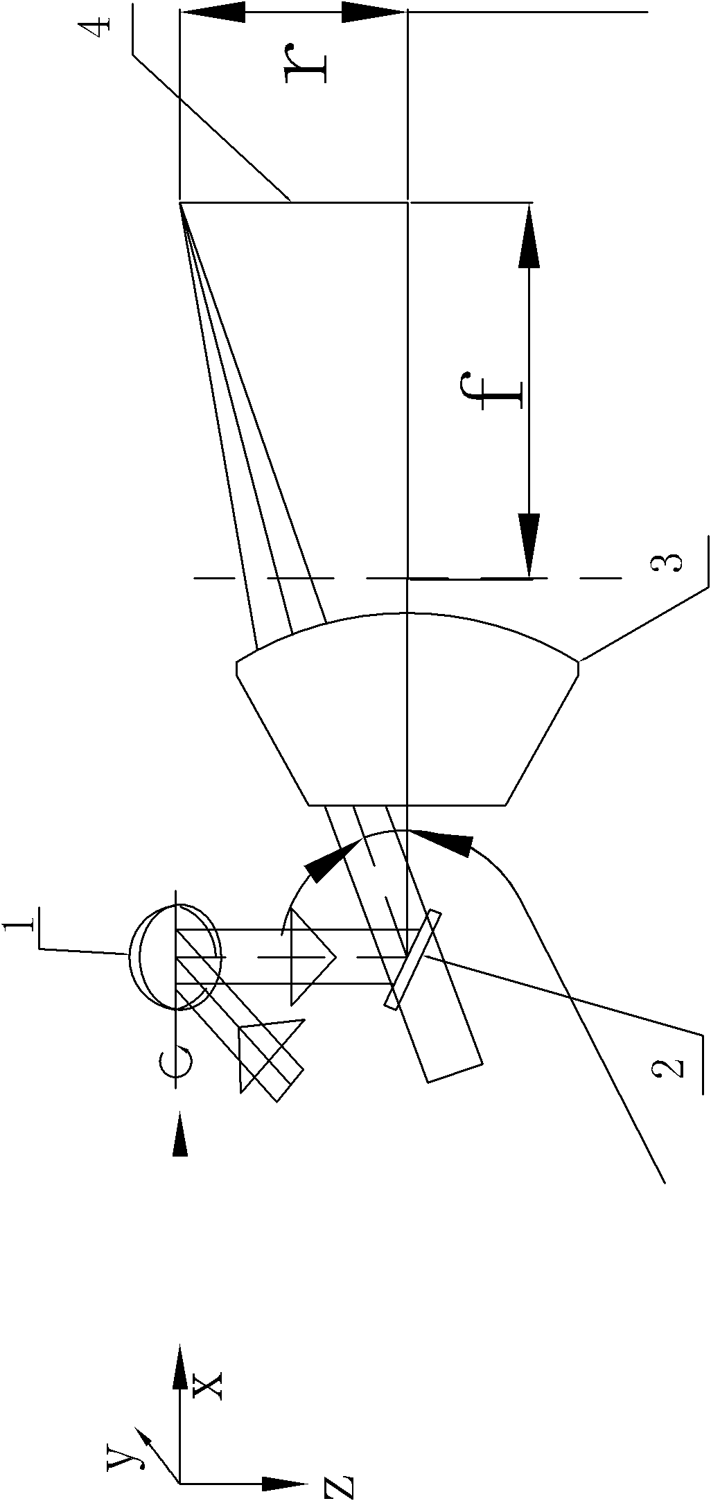
[0028] Embodiment 3, on the basis of embodiment 1 or embodiment 2, an optical system is provided, such as figure 1 , 2 As shown, it includes a galvanometer system that can rotate around the X-axis and Y-axis and guides the beam to scan on the F-theta lens 3, wherein the galvanometer system includes a first galvanometer 1 and a second galvanometer 2, and the F-theta lens 3. It includes the first lens L1 and the second lens L2 arranged in sequence along the direction of light propagation, the first lens L1 is a meniscus negative lens, the second lens L2 is a meniscus positive lens, and the curved surfaces are all facing the light incident direction Curved; the field angle of the lens is 2ω=70°, the light entrance aperture is 30mm, and the scanning range is 608mm×608mm.
[0029] The focal lengths of the first and second lenses respectively meet the system focal length of the F-theta lens:
[0030] -1.2
[0031] 0.5
[0032] Wherein, f1 is the focal length of ...
PUM
 Abstract
Description
Claims
Application Information
 - R&D
- Intellectual Property
- Life Sciences
- Materials
- Tech Scout
- Unparalleled Data Quality
- Higher Quality Content
- 60% Fewer Hallucinations
Browse by: Latest US Patents, China's latest patents, Technical Efficacy Thesaurus, Application Domain, Technology Topic, Popular Technical Reports.
© 2025 PatSnap. All rights reserved.Legal|Privacy policy|Modern Slavery Act Transparency Statement|Sitemap|About US| Contact US: help@patsnap.com


