Garbage drying device

A drying device and garbage technology, applied in the direction of combustion method, combustion type, incinerator, etc., can solve the problems of inconvenient entry and exit of garbage, inability to process, large energy consumption, etc., achieve convenient and simple garbage input and discharge, improve the effect and The effect of high efficiency and large amount of garbage drying

Inactive Publication Date: 2013-01-02
福州家禾机电成套设备有限公司
View PDF10 Cites 8 Cited by
  • Summary
  • Abstract
  • Description
  • Claims
  • Application Information

AI Technical Summary

Problems solved by technology

The existing garbage drying technology consumes a lot of energy, which is neither energy-saving nor environmentally friendly. There is a serious waste of resources, and the gains outweigh the losses
For example, the published patent "Garbage Storage Device" (Patent No. 201020612078.6) uses boiler steam to heat the garbage storage through the pipeline, and installs a cooling device to increase the air temperature in the storage. Steam can be used for other purposes and cannot be classified as waste gas; besides, steam itself contains a lot of water and is not suitable for drying garbage
Another example is "garbage drying equipment" (patent No. 200420025023.X), although waste gas from waste incinerators can be used to dry waste, but it needs to go through a complicated air preheater and the drum dryer mentioned above. It is very inconvenient to get in and out of the garbage, and it cannot handle a large amount of garbage that needs to be incinerated, which makes the incinerator work inefficient, making it impractical and unable to be popularized and applied; at the same time, the reason why this technology cannot be promoted is that the air preheater and the drum The structure of the dryer is complicated, the cost is high, and it is difficult to manufacture

Method used


Image

  • Garbage drying device
  • Garbage drying device
  • Garbage drying device

Examples


Embodiment Construction

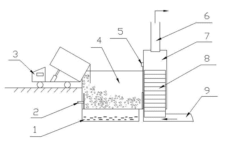
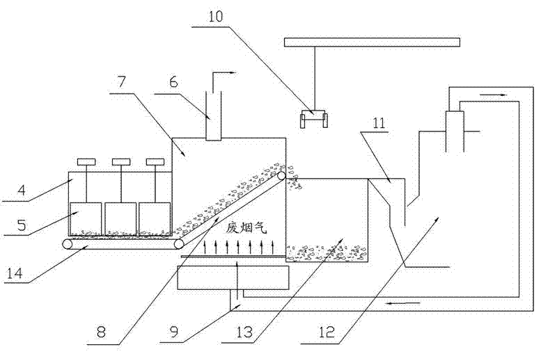
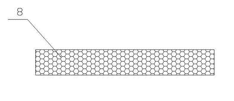
[0019] As shown in the attached figure, it is a garbage drying device, especially a device for effectively drying garbage by using waste gas from garbage incineration. Including garbage infiltration tank 1, garbage extrusion device 2, garbage pool 4, valve 5, smoke exhaust pipe 6, drying bin 7, upper conveyor belt 8, horizontal conveyor belt 14, incineration flue gas pipeline 9, garbage crane grab Bucket 10, incinerator garbage feed port 11, garbage incinerator 12, dry garbage storage bin 13.

[0020] In this embodiment, the garbage infiltration tank 1 is arranged below the garbage tank 4, and the bottom of the garbage tank 4 is a metal mesh, so that the garbage washing and squeezing filtrate can be easily dropped into the garbage infiltration tank 1, and the leachate is environmentally friendly. Utilize or discharge after treatment.

[0021] In this embodiment, a garbage extruding device 2 is provided at one end of the garbage inlet of the garbage pool 4 of the garbage dryin...


PUM


Abstract

The invention relates to a garbage drying device which comprises a garbage diffusion tank, a garbage extrusion device, a garbage tank, a valve group, a smoke discharge pipeline, a drying bin, an upward conveying belt, a horizontal conveying belt, a burning smoke pipeline, a garbage hoist grab bucket, a burning furnace garbage feeding port, a garbage burning furnace and a dry garbage storage tank. Waste gases generated by the garbage burning furnace enter the drying bin through the smoke pipeline, hot air evaporates garbage moving on the upward conveying belt and takes away steam, garbage in unit can be dried by the hot air in enough time from the bottom of the upward conveying belt to the top end of the upward conveying belt, and dried garbage is conveyed to the dry garbage storage tank or directly conveyed to the burning furnace garbage feeding port to be burned. The garbage drying device is good in drying effect, low in manufacture cost, simple and convenient in garbage feeding and discharging, large in garbage drying amount, energy-saving, environment-friendly and economic, does not need other energy for assisting, uses burned smoke as the heat source, and is especially suitable for being used in large garbage burning places.

Description

technical field [0001] The invention relates to a garbage drying device, in particular to a garbage drying device which utilizes incineration waste heat in a large garbage incineration field. Background technique [0002] The treatment method of domestic waste has developed from the original landfill to waste incineration. Because of its remarkable effect on waste treatment, it can effectively realize the reduction and resource utilization of waste, and it has received great attention. However, in order to improve the incineration effect To create conditions for subsequent energy utilization, it is necessary to dry domestic waste before incineration. The existing garbage drying technology consumes a lot of energy, which is neither energy-saving nor environmentally friendly. There is a serious waste of resources, and the gain outweighs the gain. For example, the published patent "Garbage Storage Device" (Patent No. 201020612078.6) uses boiler steam to heat the garbage storag...

Claims


Application Information

Patent Timeline
Patent Type & Authority Applications(China)
IPC IPC(8): F23G5/04F23G5/46F23G5/44
Inventor 蔡钟坤
Owner 福州家禾机电成套设备有限公司
Why Eureka
Try Eureka