Check patentability & draft patents in minutes with Patsnap Eureka AI!

Household appliance circuit arrangement

A technology for household appliances and electrical appliances, applied in circuit devices, instruments, electrical components, etc., to solve problems such as failure to meet energy consumption standards

Active Publication Date: 2013-01-09
ELECTROLUX HOME PROD CORP NV
View PDF5 Cites 3 Cited by
  • Summary
  • Abstract
  • Description
  • Claims
  • Application Information

AI Technical Summary

Problems solved by technology

[0007] This type of system has the disadvantage of having to keep powering the main electronic control unit at a low voltage. As a result, the energy consumption, although reduced, does not meet the requirements of previous generation home appliance energy consumption standards, which require appliances to consume less than 1 watt of standby power.

Method used


Image

  • Household appliance circuit arrangement
  • Household appliance circuit arrangement
  • Household appliance circuit arrangement

Examples


Embodiment Construction

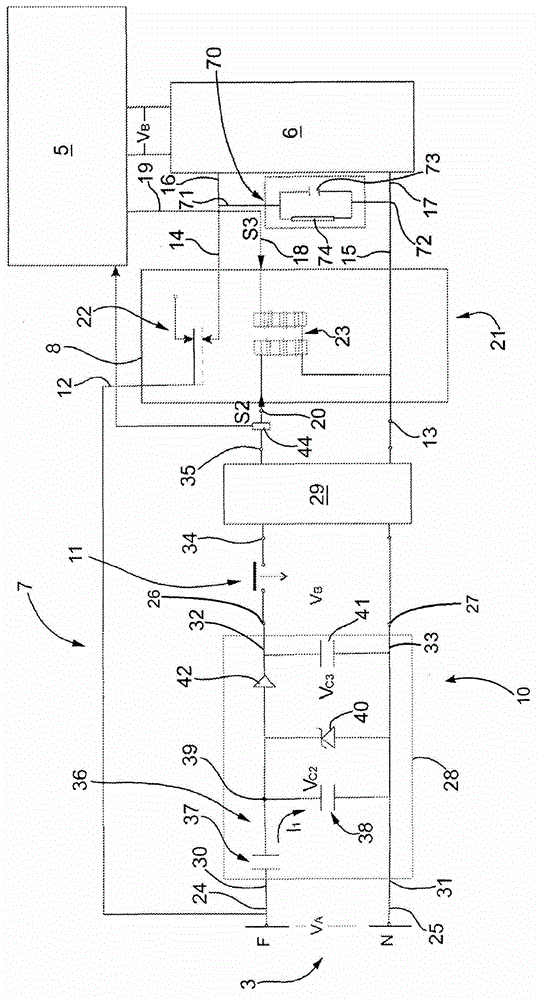
[0038] figure 1 , figure 2 and image 3 The number 1 in indicates generally a household appliance (shown schematically) connected to an electricity network 3 containing a reference potential V REF The neutral line N and the phase line F at phase potential V1.

[0039] In the example shown, the potential V of the neutral wire N and the phase wire F REF and V1 are set to obtain an alternating main supply voltage V of roughly 220V to 230V A .

[0040] The appliance 1 comprises: electronics (preferably a control unit) 5; A The input and is connected with the electronic device 5 to supply it with a low supply voltage V, for example about 4 volts to 12 volts B The output of the low voltage power unit 6.

[0041] The appliance 1 also comprises means 7 for reducing the standby energy consumption of the appliance 1 , which in turn comprise switching means 8 located between the phase line F and the neutral line connecting the low-voltage power unit 6 to the electricity network 3...


PUM


Abstract

1) An electric household appliance comprising low-voltage capacitive power means (10) connected to the electrical power network (3) and designed to generate a low-voltage (S2,V2), characterized in that said low-voltage capacitive power means (10) comprise a capacitive dividing circuit (28) comprising a first (30) and second input terminal (31) connected to a first and second power line (3) at a first (V1) and second (VREF) predetermined potential respectively; a first output terminal (32) adapted to generate said low-voltage enabling signal (S2); first (37) and second charge-accumulating means (38) connected between said first and second input terminal; and at least one voltage limiter (40) connected parallel to said second charge-accumulating means (38) and designed to switch from a non-conducting to a conducting state when subjected to a voltage above a predetermined breakdown voltage (VZ); said first (37) and second charge-accumulating means (38) being so designed that the voltage (VC2) at the terminals of said second charge-accumulating means (38) is below said predetermined breakdown voltage (VZ ).

Description

technical field [0001] The invention relates to the circuit arrangement of domestic appliances. Background technique [0002] According to the invention, the circuit arrangement is configured to generate a low voltage, preferably in the form of a pulse-type low voltage signal, which is supplied to devices of the household appliance at a negligibly small power consumption, preferably less than 10 mW. [0003] This circuit is particularly advantageous for reducing the standby mode energy consumption of household appliances. [0004] It is known that some domestic appliances of the previous generation are designed to switch into a standby or rest mode until commanded to restart the operating cycle. [0005] The electrical load of the appliance in the standby mode and the energy consumption of the main electronic control unit are relatively high although lower than in the operating mode. [0006] Accordingly, systems have been conceived for reducing standby mode energy consump...

Claims


Application Information

Patent Timeline
Patent Type & Authority Applications(China)
IPC IPC(8): G05F3/18G06F1/32
CPCH02J9/005H02M7/05Y02B70/30Y04S20/20
Inventor G·洛维索托H·多里戈F·德鲁卡
Owner ELECTROLUX HOME PROD CORP NV
Features
  • R&D
  • Intellectual Property
  • Life Sciences
  • Materials
  • Tech Scout
  • Unparalleled Data Quality
  • Higher Quality Content
  • 60% Fewer Hallucinations
Learn More