
Online detection tester for rotary drive pair mechanism
A technology of transmission pair and experimental machine, applied in the direction of machine gear/transmission mechanism testing, etc., can solve problems such as single function, and achieve the effect of convenient and fast change
- Summary
- Abstract
- Description
- Claims
- Application Information
AI Technical Summary
Problems solved by technology
Method used
Image

Examples
Embodiment Construction
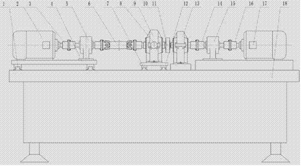
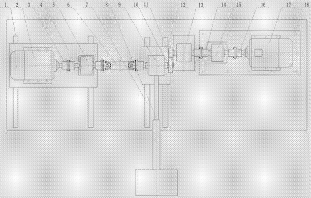
[0017] During specific implementation, an on-line detection test machine for a rotating transmission pair mechanism includes: a first guide rail 1, a first drive motor 2, a first rigid coupling 3, a first support plate 4, a first torque sensor 5, and a first torque sensor 5. To the coupling 6, the second guide rail 7, the loading electric cylinder 8, the first headstock 9, the second support plate 12, the second headstock 13, the second rigid coupling 14, the second torque sensor 15, the third Rigid shaft coupling 16, the second drive motor 17 and support 18 and acceleration sensor, temperature sensor, displacement sensor and pressure sensor; Wherein, described first guide rail and second guide rail are arranged on support 18 in parallel; Said The first drive motor 2 and the first torque sensor 5 are connected through the first rigid coupling 3, and both are fixed together on the first support plate 4, and the first support plate 4 is slidably arranged on the first guide rail 1...
PUM
 Abstract
Description
Claims
Application Information